Defect Detection
Handheld imager projects fringe patterns onto the surface of machined parts, allowing precision nondestructive measurements of aerospace components
Andrew Wilson, Editor
Since machined parts such as turbine airfoils and compressor fans may have edges shaped for achieving specific mechanical functions, it is vital that these surfaces be free of defects and manufactured to the correct shape. In the past, measurement of edge breaks or similar small features (such as pits or scratches) on these parts was made by taking a wax or soft metal impression of the edge and measuring the impression using a mechanical gauge. Because this is both time-consuming and inexact, General Electric Global Research Center (GE) and Optics for Hire have developed a handheld measurement tool that uses a structured light projector coupled with an optical viewer to image these defects.
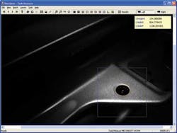
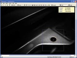
“In the past,” says John Ellis, president of Optics for Hire, “devices for performing noncontact 3-D surface profiling with structured light patterns have not been used in manufacturing environments for this type of measurement since they were not easily portable, often requiring a fixed bench setup. Because of this, service personnel could not quickly and accurately inspect parts on the shop floor." To overcome these limitations, Kevin Harding of GE teamed up with Ellis and his colleagues to develop a portable device capable of making precision measurements of manufactured parts (see Fig. 1).
Structured light
In the design of the handheld imager, structured light patterns are first projected on the object to be tested. These are then digitized and analyzed to produce a 3-D profile of the surface of the part. To accomplish this, light from a built-in red LED from Norlux first passes through a condensing lens that concentrates it into a cone of light, which then illuminates a Ronchi grating with parallel beams of uniform intensity. As an optical target with constant-interval bars and spaces, light intensity passing through the Ronchi ruling varies as a square waveform with fundamental sinusoidal and harmonic components that define the sharp intensities in the square wave.
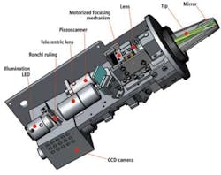
"Because the harmonic components of the light will result in extraneous interference patterns that would otherwise appear on the surface of the part," says Harding, “they must be removed from the optical path." To accomplish this, the harmonic components are diffracted by the Ronchi ruling to angles that increase with frequency. As a result, they can be removed by an imaging aperture placed in the optical path (see Fig. 2).
After removal, three different images are projected onto the part to generate a 3-D map of its surface. Using a method known as phase-shift analysis, these three reflected structured patterns can then be employed to provide a map of 3-D points and range information of every pixel in the 3-D image. "This phase-shifting method is robust to surface finish issues and tolerant of noise generated by surface markings or reflections due to color or finish," says Ellis.
This technique requires the use of three images to be projected onto the part, so images from the Ronchi ruling are reflected from a mirror. Mounted in the optical axis on a piezoelectric motor from Piezosystem Jena, this piezoelectric-driven mirror is used to move the illumination pattern on the part by 1/3 of a grating period. Since the grating period and absolute movement change slightly with distance, a constant amount of phase shift is achieved.
Phase maps
By capturing three images at three different but known phase shifts, a phase map of the surface of the part can be calculated with the phase at each point being directly proportional to the range of the part. This phase information is then be used to generate an x-y-z coordinate system of the part's surface.
Using the phase-shift tilt method minimizes the number of images needed, so the data can be captured in under half a second. However, if there is a step change in the field being measured, the image analysis can lose track of the surface and the size of the step cannot be computed. In the case of surface turbine blade measurement, for example, the measurement depth is relatively small, and feature differences are all typically less than the interval covered by one fringe movement.
As these images are projected onto the part, they are digitized by a viewer that is also incorporated into the handheld imager. In operation, diffuse reflected light from the part is imaged by the viewer's optics, offset from the axis of the projector. “By offsetting the optical axis of the projector and viewer,” says Harding, “diffusely reflected light will be captured without any interference from specularly reflected light."
Diffuse reflection of the structured light patterns is then captured using an embedded Allied Vision Technologies' Prosilica EC1380-D, a CCD camera that incorporates Sony's ICX285 with 1360 × 1024, 6.45 × 6.45-µm pixels. Using the FireWire output from this camera, the three captured images are transferred to the host PC.
To ensure that the projected light pattern is correctly focused and captured, linear voice coil actuators designed by Optics for Hire are used to synchronously move two lenses in both the projector and viewer. The operator can manually focus these lenses onto the part being examined using control buttons in the handle of the measurement tool. To aid in the measurement of difficult-to-image parts, the gauge also allows a number of different mirror tips to be attached to the projector. "In this way," says Ellis, "the tool can be used to inspect parts with complex angles or curvatures."
Three-dimensional images
In the images that are captured, wavefront phase differences are encoded as light-intensity variations of the captured fringes. Using software developed in-house at GE, these fringes are then filtered, unwrapped, and analyzed. "This analysis assumes that the user of the instrument first chooses limits on the depth and width of feature of interest, for example, features that are 0.001 in. in depth and width or larger," says Ellis.
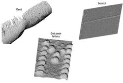
After the limits are set, the software fits a freeform surface such as a cylinder, parabola, or saddle point to the data, allowing the generation of a 3-D image that shows the part and any defects that may be present (see Fig. 3). The surface fit also provides a measurement of the radius and shape of an edge.
FIGURE 3. After wavefront phase differences are unwrapped, PC-based software fits a freeform surface such as a cylinder, parabola, or saddle point to the data, allowing a 3-D image of the part to be generated.
The analysis then finds the deepest defect relative to this surface, as well as the number of defects represented as continuous blobs that are above the set limits. The user can toggle through all the defects to find the depth, area, and aspect ratio of each one.
To evaluate the gauge repeatability and reproducibility (GR&R) of the instrument, GE performed a Six Sigma evaluation; at a handheld working distance with a 0.125-in. field of view, the achievable repeatability was better than 10% for a process tolerance of 0.005 in. and a resolution of about 0.0001 in.
According to Ellis, the handheld gauge has been evaluated at a number of GE facilities worldwide for the inspection of turbine blades and other machined aerospace parts.
Company Info
Allied Vision Technologies
Stadtroda, Germany
www.alliedvisiontec.com
General Electric Global Research Center
Niskayuna, NY, USA
www.ge.globalresearch.com
Norlux
Carol Stream, IL, USA
www.norluxcorp.com
Optics for Hire
Arlington, MA, USA
www.opticsforhire.com
Piezosystem Jena
Jena, Germany
www.piezojena.com


