Applying vision to nozzle-plate analysis
Combining vision and motion-control techniques automates and accelerates the inspection of semiconductor print-head devices.
By Andrew Wilson,Editor
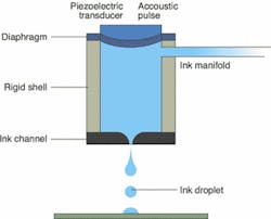
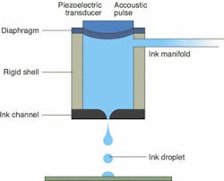
For a number of years, microelectromechanical-system processes have been used to manufacture piezoelectric print heads that contain hundreds of ink-filled chambers connected to the surface of the chip by microscopic nozzle channels etched in silicon. These processes integrate mechanical elements, sensors, actuators, and electronics on a silicon substrate using standard CMOS, bipolar, or BiCMOS technologies. Etching parts on the silicon wafer or adding structural layers to produce combined mechanical and electromechanical devices form micromechanical components. In the print-head design, a piezoelectric element located at the back of the ink reservoir forces the ink through the nozzles.
FIGURE 1. Measuring approximately 32 mm long and 1 mm wide, ink-jet nozzle plates are machined as microelectromechanical systems. Ink flows into the ink-jet nozzle plate through several openings on the side of the part. When the piezoelectric device is triggered, the ink is fired through approximately 1000 orifices along the length of the device. (Courtesy Litrex Corp.)
When the piezoelectric crystal element receives an electric charge, it vibrates inward and forces ink out of the nozzle. As the element vibrates back, more ink is drawn into the reservoir. With each plate measuring approximately 32 mm long and 1 mm wide, a single 6-in. wafer might hold as many as 200 nozzle plates. During operation, ink flows into the ink-jet head through several openings on the side of the nozzle plate. When the piezoelectric device is triggered, the ink is fired through approximately 1000 orifices along the face of the nozzle plate (see Fig. 1).
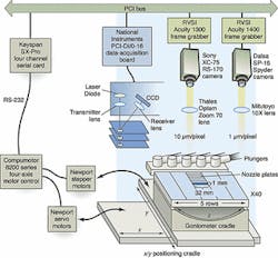
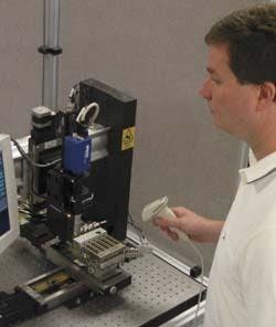
Automated inspection"In the manufacture of these devices, it is critically important to check each orifice for any process contamination that may occur during manufacturing," says Yair Kipman, president of ImageXpert (Nashua, NH). "Such defects may manifest themselves as clogged ink-jet nozzles from the wafer-sawing procedure. Other defects can include rough or cracked edges that will result in random ink dispersion, causing image streaks to appear on the end user's printed document," he adds.To automatically detect these defects, ImageXpert developed a cleanroom-compatible inspection system. This automated Front Face Inspection System uses off-the-shelf cameras, frame grabbers, data-acquisition boards, motor controllers, and machine-vision software. Up to 200 nozzle plates are loaded into a magazine cassette in five rows of 40 nozzle plates each. After the cassette is loaded, it is secured in a positioning cradle within the inspection system (see Fig. 2).
"Before any automated inspection can begin," says Kipman, "it is necessary to firmly fix the 200 plates in the cassette." To accomplish this task, a set of five pneumatically controlled actuators forces five plungers into the cassette housing; this action eliminates any gaps that may exist between the nozzle plates. After fixturing, a fiducial mark on the cassette precisely positions the cassette inx-y space. By image-capturing the location of this fiducial mark, the positions of the nozzle plates can be computed from the known dimensions of the cassette.
Finding fiducialsTo find the fiducial mark, the field of view of the system camera needs to be wide, but high resolution is not required. As a result, a standard XC-75 RS-170-based CCD camera from Sony (Park Ridge, NJ) is coupled to a Zoom 70XL 7:1 zoom lens system from Thales Optem (Fairport, NY) to provide a resolution of 10 µm/pixel and a field of view of approximately 3 cm.FIGURE 3. Under software control, the cassette tray is moved on an x-y table to position the camera over a known fiducial mark. To perform this task, a PCI-based serial communications card running under the Mac OS controls a four-axis motor controller that, in turn, drives the servo motors that power the x-y table.
Positioning the cassette tray under the fiducial mark is performed by a motion-control system hosted by the same PowerPC for the imaging system. Under software control, the cassette tray is moved on a UT150x-y table from Newport Corp. (Irvine, CA) to position the camera over the fiducial mark. A PCI-based SX Pro Serial communications card from Keyspan (Richmond, CA), running under the Mac OS, controls a 6200 Series four-axis motor controller from the Parker Hannifin Compumotor Division (Rohnert Park, CA). This controller, in turn, drives the servomotors that power the UT-150 x-y table (see Fig. 3).
Once the fiducial mark is located, the positions of the orifices can be inspected. "However," says Kipman, "because any difference in the height of each part in the cassette along its 32-mm length will cause captured images to be out of focus, the system must compensate for any nonlinearity in z-space." Consequently, accurate, high-resolution measurements of the height and angle of the parts must be made. The height and angle are adjusted automatically via a computer-controlled goniometer and the z-axis camera stage.
To perform this task to a resolution of 1 µm and a linearity of ±0.1% full scale, the inspection system uses an LK series laser distance-measurement sensor meter from Keyence (Woodcliff Lake, NJ). Using a CCD sensor as the light-receiving element, laser light reflected by each print head passes through a receiver lens to a CCD that detects the peak value of the light quantity distribution of the beam spot. Analog output signals representing this peak value for multiple points along the part are then output to a PCI-DI/O data-acquisition board from National Instruments (Austin, TX) and to the host PowerPC's system memory. In this way the system produces anx, y map of the position of each part and ensures proper height and angle (z).
High-resolution imagingOnce this map is computed, images of each nozzle plate must be captured at high resolution. A second imaging system is needed that uses a 10X lens from Mitutoyo America (Aurora, IL) attached to a Spyder SP-16, 2048 X 1-pixel, 40-MHz linescan camera from Dalsa (Waterloo, Ont., Canada) with an LVDS output. To capture images with this camera, the ImageXpert Front Face Inspection System uses the RVSI Acuity CiMatrix (Canton, MA) PCI-based 1400 series frame grabber, which is also integrated into the Power PC."Unlike the fiducial registration stage, where servo motors could be used to rapidly position the Sony camera over the area of interest without impacting the results," says Kipman, "the high-resolution 1-µm/pixel imaging requirements of each nozzle plate demand a motorized system that can assure part position and alignment in the z direction." Using the same Compumotor 6200 motor controller used for thex, y positioning, engineers at ImageXpert chose to drive the Newport UT-100 goniometer stage of the cradle with Newport stepper motors.
During operation, each part is leveled prior to imaging. Since focus is critical to the success of the process, the system compensates for any deviation in the z-axis before each 32-Mbyte image is captured. Data from the height (z) measurements are used as input to the motor controller and the goniometer stage. Once the part is leveled and the height of the camera is adjusted for focus, the part is moved under the linescan camera for image capture. After an image of the entire nozzle array on a single part is captured, image analysis is performed while the next part is being leveled and the next image is being captured. Parallel image capture and processing increase system efficiency.
"Because of the large, high-resolution images and precision control required of the Front Face Inspection System," says Kipman, "it can take between 20 and 40 minutes to image all of the parts in a cassette of nozzle plates." As the machine-vision process continues, a map of defective parts due to clogs and cracks is constructed. Other features, such as the position of each orifice and their diameters and circumferences, are measured against tolerances and are saved in a data file.
ImageXpert chose to base its inspection system on a machine-vision software package offered by RVSI Acuity CiMatrix. The Powervision platform includes the mature image-analysis and motion-control capabilities that this application required. "Powervision allows us to combine both a linescan and 2-D CCD camera in this system," says Kipman. "Because this system is for use in a production environment, integrated optical-character recognition and barcode decoding (both 1-D and data matrix) allow us to automate data file naming by part ID."
Once the imaging and motion process is complete, the cassette is removed from the system and another cassette is inserted. The inspected cassette is moved to a pick-and-place machine, which shares a data network with the Front Face Inspection System. The data map of dispositioned parts is passed to the pick-and-place machine, which uses the data to place acceptable nozzle plates into the queue for the next level of print-head assembly. Parts that fail the automated inspection are discarded by the pick-and-place machine.
Company InformationDalsaWaterloo, Ont., Canada N2V 2E9www.dalsa.comImageXpertNashua, NH 03063www.imagexpert.comKeyence Corp. of AmericaWoodcliff Lake, NJ 07675www.keyence.comKeyspanRichmond, CA 94806www.keyspan.comLitrex Corp.Pleasanton, CA 94588www.litrex.comMitutoyo AmericaAurora, IL 60504www.mitutoyo.comNational InstrumentsAustin, TX 78759www.ni.comNewport Corp.Irvine, CA 92606www.newport.comParker HannifinRohnert Park, CA 94928www.compumotor.comRVSI Acuity CiMatrixCanton, MA 02021www.rvsi.comSonyPark Ridge, NJ 07556bssc.sel.sony.com/ProfessionalThales OptemFairport, NY 14450www.thales-optem.com


