Vision inspection bares acrylic-sheet defects
Custom and commercial hardware and software are integrated into a vision-inspection system that detects miniscule flaws in acrylic sheets.
By Fabio Perelli
Acrylic sheet can be transformed into a variety of products. To ensure quality, any defects must be found prior to shipping to save production, handling, and reject costs. However, reliable and accurate acrylic-sheet inspection proves difficult because the sheets measure up to 3 × 2 m, and defects can be small, for example, on the order of 0.5 mm.
APS Vision Ltd. (Sunderland, UK), a systems integrator, was approached by an acrylic-sheet manufacturer to develop and automate a vision-inspection system to solve its defect problems. Based on the manufacturer's requirements, the company designed OASIS (optical acrylic-sheet-inspection system), which uncovers a variety of faults in sheets of cast acrylic (see Fig. 1).
Manufacturing process
Acrylic sheets are made by a process known as cell casting. During processing, glass cells, which are essentially two sheets of glass, are filled with a polymerized liquid. A gasket is placed on the outside sheet edges to prevent leaks. The cells are then "split open" to create the acrylic sheet. Next, they are inspected and protected by a polythene film. Lastly, the glass cell is refilled for the next batch.
Producing the acrylic sheets with this method permits an extensive product range that can be made in relatively small batches with little transition waste. The sheets also can be made in a number of sizes and thicknesses; moreover, pigments can be added to the polymerized liquid to produce sheets in various colors.
Even with this flexible manufacturing process, however, numerous defects can appear in the cast sheets. Problems include contamination, surface defects imprinted from the glass, bubbles, liquid leaks, color separation, and polymerization faults. Another common defect, the 'blowout,' appears as a bubble and normally occurs at the edges of the sheet where, under pressure, the acrylic leaks out between glass cells.
Vision inspection
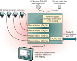
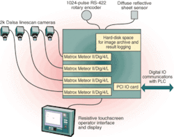
After studying the production process, APS Vision designed the OASIS vision-inspection system. This system comprises a 19-in. rack-mounted industrial PC from SightSystems Ltd. (West Sussex, UK), which contains a 1-GHz Pentium 4 processor and four Meteor-II/digital frame-grabber boards from Matrox Europe Ltd. (Buckinghamshire, UK). Each frame grabber is connected to an SP-14-02k30 Spark Camera from Dalsa (Waterloo, ON, Canada) and Firstsight Vision Ltd. (Surrey, UK). Each camera is fitted with a 90-mm lens from Tamron USA (Commack, NY, USA) and FirstSight Vision.
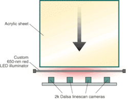
All four linescan cameras are synchronized to a 1024-pulse/revolution RS-232 rotary encoder from Baumer Electric (Swindon, UK) to accommodate the speed variations of the production line. A digital PCI I/O card from Arcom Controls (Cambridge, UK) is used to synchronize the system with the production line via an Allen Bradley (Milwaukee, WI) programmable logic controller (PLC). Illumination is provided by a custom 2.2-m-long, 650-nm, red LED light line (see Fig. 2). User system interfacing is accomplished with an LCD resistive touch screen from Trident Microsystems Ltd. (Surrey, UK).
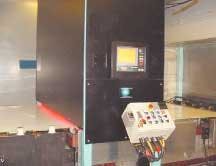
During operation, the OASIS system automatically inspects each acrylic sheet as it passes from the washing stage to the wrapping machine (see Fig. 3). Before a new batch is inspected, the system operator configures the inspection parameters using the LCD touch screen. Through a series of option screens, the operator specifies such inspection criteria as sheet size, color, and thickness.
Then, as the acrylic sheet enters the inspection workcell, its leading edge trips a diffuse reflective sheet sensor. This action signals the vision system to start acquiring video from the linescan cameras. As the sheet moves along the conveyor, the rotary encoder generates trigger pulses for all four cameras. Without the encoder, speed variations of the conveyor could either stretch or compress some features in the acquired images.
The necessary image resolution requires approximately 8000 pixels across the 2-m width of the sheet. The four 2048 × 1-pixel cameras minimize the parallax problems that would arise with the use of an 8k-pixel camera and are arranged in a row with a small coverage overlap between each camera. Data are simultaneously grabbed from all four cameras to form four images that span the entire width of the sheet. The size of each image is determined by the length of the sheet being inspected; the largest-sized sheets render approximately 90 Mbytes of captured image data.
Defect search
To search for surface defects, APS Vision's custom application software uses Matrox Imaging Library (MIL) software to locate the edges of the sheet. Then, a "don't care" region is specified and imaged around the edge of the sheet that includes the specified width of the gasket. Defects found within this region are removed when the distributor cuts the acrylic sheet to size.
The remainder of the sheet is considered the region of interest, where the software applies a Sobel edge detector. The resultant image is thresholded to remove noise points while retaining maximum edge sensitivity. Next, this binary image is processed by a blob-detection routine that classifies the blobs based on certain characteristics, mainly area and dimensions. If any blobs are classified as failures, the sheet is rejected.
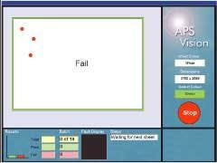
If a defect is located, the system stops for a manual inspection (see Fig. 4). Locations of the defects on the sheet are displayed on the LCD touch screen by a red dot. When the operator touches the red dot, a thumbnail image of the defect is displayed. After examining the fault, the operator must decide if it can be removed (see Fig. 5). Dirt, for example, can be brushed away. Deep scratches, however, might render the sheet unusable.
The variety of production acrylic sheets imposed design challenges for the APS Vision engineers. For instance, sheet thickness can vary between 3 and 12 mm, and this variation presented difficulties with illuminating the system. Conventional fiberoptic-type light lines produce an intense light in a narrow beam, but these devices proved unsuitable for this application. As the thickness of the sheet changes, the position of the beam moves in such a way that very little light falls within the lines of sight of the cameras.
To counteract this problem, APS Vision designed a custom LED illuminator that produces a broad directional beam, yet remains unaffected by the thickness of the sheet. A key advantage of this illuminator is that the LED offers a substantially longer lifetime than fiberoptic light sources do; therefore, downtime of the illuminator becomes minimal. The illuminator is made up of 15 printed-circuit boards (PCBs), each containing 168 ultrabright-red LEDs. The PCBs are mounted in a steel channel with a diffuser placed over the front surface. The illuminator unit comes with two fans (one at each end) arranged in a push-pull configuration to ensure that the entire unit is kept cool. Power consumption for the light line is 100 W.
Not only are the acrylic sheets produced in a range of colors, but they can be made transparent or opaque. These parameters require the vision-inspection system to support a wide dynamic range. "This was an important constraint for the cameras," explains APS Vision systems engineer Adam Brown. "It was also important that the selected frame-grabber/camera combination allow fine software control over the exposure. With the Matrox Meteor-II frame grabbers, we are able to vary the exposure from approximately 3 µs to 3 ms in steps of 50 ns."
Since the gray-scale level of the image varies when the sheet color changes, basic thresholding techniques are not feasible. Instead, after locating the edges of the sheet, the entire sheet surface is processed by a Sobel edge-detection algorithm. This process produces candidate points that may belong to defects. These points are further processed by a blob detection algorithm that separates out false negatives from genuine failures.
Says Brown, "Software support is an important factor for us. This was why the Matrox Imaging Library was chosen to coordinate the system's image-acquisition, camera-control, and image-processing functions. And image-analysis algorithms are used to locate the edges of the sheet in each camera view." APS Vision plans to adapt the OASIS for similar discreet sheet- and web-inspection applications, such as inspecting sheets of glass, metal, and laminates.
FABIO PERELLI is product manager, frame grabbers and stand-alone systems, Matrox Imaging, Dorval, QC, Canada; www.matrox.com/imaging.
Company Info
Allen Bradley www.ab.com
APS Vision Ltd. www.apsvision.com
Arcom Controls www.arcom.co.uk
Baumer Electric www.baumerelectric.com
Dalsa www.dalsa.com
Firstsight Vision Ltd. www.firstsightvision.co.uk
Matrox Europe Ltd. www.matrox.com/imaging
SightSystems Ltd. www.sightsystems.co.uk
Tamron USA www.tamron.com
Trident Microsystems Ltd. www.trident-uk.co.uk
