Camera vendors split on digital interface standards
By Andrew Wilson,Editor
Point-to-point and bus-based standards are vying for position as digital camera-interface standards
In the past, camera vendors offered analog outputs to their sensors, leaving frame-grabber manufacturers to develop high-speed camera interfaces. But as high-speed analog-to-digital converters and analog front ends become less expensive, camera manufacturers are choosing to integrate more and more functionality into their cameras.
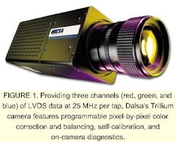
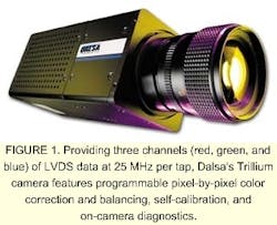
FIGURE 1. Providing three channels (red, green, and blue) of LVDS data at 25 MHz per tap, Dalsa's Trillium camera features programmable pixel-by-pixel color correction and balancing, self-calibration, and on-camera diagnostics.
By offering digital outputs, these cameras increase the noise immunity of sensors on the factory floor, allow longer cable lengths from camera to host computers, and eliminate the need for analog PCI-based interfaces. With the move toward digital camera interfaces, camera vendors must decide whether to support point-to-point communication standards such as RS-644 and Camera Link or bus-based solutions such as IEEE-1394 and Fibre Channel.
Build on standardsMany of today's cameras support the RS-644 standard, a low-voltage-differential-signal (LVDS) protocol that extends the performance of the RS-422 differential data bus. Although compatible with RS-422, the RS-644-based devices require less power, permit longer cable lengths, provide faster clock rates, and offer improved electromagnetic interference (EMI) characteristics (see table on p. 47). However, while RS-422-based cameras are limited to 20-MHz clock rates, LVDS clock support is more than 65 MHz, and signal transmission cable length is 30 to 100 ft.Today, many cameras and frame grabbers support RS-644 LVDS differential parallel standard for data transmission, digital data, data clocking, and control signals. For example, the Trillium color linescan cameras from Dalsa (Waterloo, Ontario, Canada) provide three channels (red, green, and blue) of LVDS data at 25 MHz per tap, programmable pixel-by-pixel color correction and balancing, self-calibration, and on-camera diagnostics (see Fig. 1). In addition, they use 10-bit ADCs and output the most significant eight bits (one channel for each color) in LVDS format.
The outputs of RGB data from color area-array and linescan cameras such as the Trillium are usually delivered in an RGB x 8-bit data format. When camera clock, horizontal and vertical syncs, control signal, and ground signals are included, a minimum of 28 cable pairs for all of the signals are needed. This cabling scheme requires the interfacing of such cameras to a minimum of 56 conductors. To do so, camera vendors use multiple RS-644 drivers and receivers in their cameras.
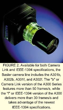
Enter Camera LinkTo reduce the number of camera ICs needed, camera vendors led by Pulnix (Sunnyvale, CA) have adopted a version of the Channel Link technology originally developed by National Semiconductor (Santa Clara, CA) to drive flat-panel displays. Based on LVDS technology, Channel Link consists of a driver and receiver pair. The driver accepts 28 single-ended data signals and a single-ended clock. Data are then serialized 7:1, and the four data streams and a dedicated clock are driven over five LVDS pairs to a receiver, where the four LVDS data streams are deserialized.FIGURE 2. Available for both Camera Link and IEEE-1394 specifications, the Basler camera line includes the A301b, A302b, A301f, and A302f. The "b" or Camera Link version of the A300 Series features more than 50 frames/s, while the "f" or IEEE-1394 version of the A300 delivers more than 30 frames/s and takes advantage of the newest IEEE-1394 specifications.
Because a single Channel Link IC is limited to 28 bits, some cameras may require several devices to transfer data efficiently. As a result, camera vendors adopted the Camera Link interface developed by Pulnix and other camera and frame-grabber vendors that offers three configurations to support various interface applications. In the base configuration, a single Channel Link IC is used with a single cable connector. In the medium configuration, two Channel Link ICs are used with two cable connectors. For the full configuration, three Channel Link ICs and two cable connectors are needed.
The Camera Link specification, available on the Web at www.machinevisiononline.org, uses the 28-bit Channel Link ICs manufactured by National Semiconductor. Devices that use a similar technology, such as Flatlink by Texas Instruments (Dallas, TX) and Panel Link by Silicon Image (Sunnyvale, CA), may not be compatible with the Camera Link interface. According to the specification, however, receivers and drivers with different operating frequencies are expected to interoperate over the frequency range that both support.
To reduce EMI effects on the digital data, power is not specified in the Camera Link specification. Because of this, vendors must develop a separate way of providing power to their cameras.
Today, RS-644 is an industrial standard for camera and frame-grabber manufacturers. Channel Link will replace this standard for high-performance digital cameras. Already, several frame-grabber manufacturers have started designing in the Channel Link specification for color, multitap linescan, and high-frame-rate cameras. At the recent Vision Show West (San Jose, CA), a number of vendors debuted products based on Channel Link technology (see Vision Systems Design, Nov. 2000, p. 7).
Typical of these is the MMV range of cameras available from illunis (Minnetonka, MN). Based on the KAI-1010 sensor from Kodak (Rochester, NY) with 9.0-µm pixels, the MMV 1010 machine-vision camera features a resolution of 1009 x 1018 x 10-bit pixels and can be clocked in either single- or dual-tap modes at 40 MHz. An available color, Bayer-pattern-version camera uses the new Camera Link LVDS data transmission interface and can operate as far as 10 m from the host computer.
Bus-based solutionsWhile high-performance, high-speed camera vendors such as Basler (Exton, PA), Dalsa, JAI (Laguna Hills, CA), and Pulnix are incorporating Camera Link interfaces into cameras, other vendors are looking for less-expensive, bus-based solutions. First introduced by Apple Computer (Cupertino, CA), the FireWire interface (now standardized as IEEE-1394) is a serial, digital, nonproprietary bus, designed to interface high-speed computer peripherals such as hard disks, CDROMs, and scanners at 800 Mbits/s.In the IEEE 1394 specification, data transfer is handled by a shielded, double-twisted-pair cable that is driven by low-amplitude differential signals. In addition, the interface includes a power line in the cable to supply power directly to low-power cameras. The bidirectional nature of this interface allows camera parameters to be changed on the fly and, some designers predict, is expected to end the need for custom configurations between digital cameras and frame grabbers.
At the Vision Show West, Basler introduced IEEE-1394 interfaces for a number of its A300 Series machine-vision cameras. Available in both Camera Link and IEEE-1394 bus versions, these cameras include the company's A301b, A302b, A301f, and A302f models. The "b" or Camera Link version of the A300 Series offers frame rates higher than 50 frames/s, while the "f" or IEEE-1394 version of the A300 delivers more than 30 frames/s and takes advantage of the newest IEEE-1394 specifications (see Fig. 2). According to Basler, these cameras allow users of RS-170 cameras to effectively realize the benefits of digital cameras.
Like every bus-based specification, however, the IEEE-1394 specification has its disadvantages. If the IEEE-1394 bus is too busy, for example, the serial data flow may be disturbed by the interaction of other devices. Accordingly, the frame speed may not remain constant and image data may be lost. Only a single, point-to-point IEEE-1394 connection can deliver constant frame speed.
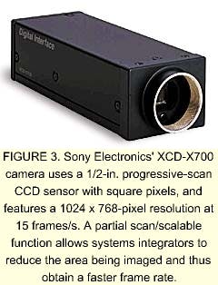
Bus contentionWhen a camera is inserted or removed from an IEEE-1394 socket, a clean connection is not immediately made, according to Bill Pearson of Intel (Santa Clara, CA). Because of this, electrical contact is made and broken many times within a very short period, and a bus reset occurs. This action creates bus resets that disrupt isochronous traffic on the bus. To overcome this, the IEEE has developed the IEEE-1394a standard to improve bus efficiency, provide arbitration acceleration, improve the speed of bus resets, and add power-management capabilities to the bus.FIGURE 3. Sony Electronics' XCD-X700 camera uses a 1/2-in. progressive-scan CCD sensor with square pixels, and features a 1024 x 768-pixel resolution at 15 frames/s. A partial scan/scalable function allows systems integrators to reduce the area being imaged and thus obtain a faster frame rate.
A proponent of the IEEE-1394 standard, Sony Electronics (Park Ridge, NJ) has introduced its XCD-X700. Weighing 250 g with dimensions of 44 x 33 x 116 mm, this camera uses a 1/2-in. progressive-scan CCD sensor with square pixels and delivers 1024 x 768 resolution at 15 frames/s (see Fig. 3). A partial scan/scalable function allows systems integrators to reduce the area being imaged and therefore increase the frame rate.
Despite the advantages of these cameras, many systems integrators find the 4.5-m cable length too short for their needs. Because of this, a supplement to the IEEE Std. 1394-1995 and IEEE Std. 1394a-2000 standards, IEEE-1934b, is under development. Although not yet standardized, the 1934b specification defines features and mechanisms that provide 1.6-Gbit/s data transfers in a backward-compatible fashion and the ability to signal over distances to 100 m. The preliminary specification is available on the Web at www.zayante.com/p1394b/ drafts/p1394b_rev100.pdf.
Frame-grabber supportAlready, a number of manufacturers have announced both IEEE-1394 and Camera Link interface cards. To support the IEEE-1394 standard, a number of companies including Procomp Informatics (Fremont, CA), Orange Micro (Anaheim, CA), and Granite Microsystems (Mequon, WI) have introduced PCI-based interface cards.Primarily developed for consumer PCs, PCI boards such as Procomp's SpeedDemon 400 are typical of those currently being offered by board-level vendors. As a 1394 PCI standard host controller card, the SpeedDemon features three independent 1394 bus ports, each of which can transfer data at 400 Mbits/s. And, because the board supports hot-plug technology, IEEE-1394 devices can be connected or disconnected without having to shut down or restart the host computer.
One of the first vendors to support the Camera Link interface, Euresys (El Cajon, CA), has introduced a PCI-based Dual Camera Link Input module. With two Camera Link-compliant connectors, the board can simultaneously acquire data from two gray-scale cameras or multiplexed acquisition from two RGB cameras. Datacell (Finchampstead, Berkshire, England) also plans to support Camera Link on its Phoenix frame grabber, a PCI-board capable of supporting both 32-bit/33-MHz and 64-bit/66-MHz PCI buses.
''While in its current state, IEEE 1394 is good for standard video resolutions and rates; Camera Link is ideal for high-resolution and/or high-rate area- and linescan cameras," says Pierantonio Boriero, product-line manager for Matrox Imaging (Dorval, Quebec, Canada). "And, just as we have supported the IEEE-1394 interface with a PCI-based product, Matrox Imaging will incorporate Camera Link into its hardware and software designs in the near future," he adds.
Company InformationDue to space limitations, this Product Focus article does not include all of the manufacturers of the described product category. For information on other suppliers of digital cameras, see the 2000 Vision Systems Design Buyers Guide (Vision Systems Design, Feb. 2000, p. 36).Apple Computer
Cupertino, CA 95014
Web: www.apple.com
Basler
Exton, PA 19341
Web: www.baslerweb.com
Dalsa
Waterloo, Ontario
Canada N2V 2E9
Web: www.dalsa.com/
DataCell
North Billerica, MA 01862
Web: www.datacell.com
Eastman Kodak
Rochester, NY 14650
Web: www.kodak.com
Euresys
El Cajon, CA 92019
Web: www.euresys.be
Granite Microsystems
Mequon, WI 53092
Web: www.granitemicrosystems.com
illunis
Minnetonka, MN 55345
Web: www.illunis.com
Intel
Santa Clara, CA 95052
Web: www.intel.com
JAI America
Laguna Hills, CA 92653
Web: www.jai.dk
Matrox
Dorval, QC H9P 2T4, Canada
Web: www.matrox.com/imaging
National Semiconductor
Santa Clara, CA 95050
Web: www.national.com
Orange Micro
Anaheim, CA 92807
Web: www.orangemicro.com
Procomp Informatics
Fremont, CA 94538
Web: www.procompusainc.com
Pulnix America
Sunnyvale, CA 94089
Web: www.pulnix.com
Silicon Image
Sunnyvale, CA 94085
Web: www.siimage.com
Sony Electronics
Park Ridge, NJ 07656
Web: www.sony.com/professional
Texas Instruments
Dallas, TX 75266
Web: www.ti.com


