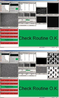
Machine-vision workcell checks auto interiors
Multiple cameras, frame grabbers, and lighting assemblies team up to ensure car-seat quality.
By Andrew Wilson, Editor
Andrew Waller, a director with Industrial Vision Systems (IVS), says, “Automakers outsource their interior-system requirements to maximize quality and reduce costs. Not only do the companies manufacture auto interior systems, they design them, integrate them, and deliver them to locations around the world.” And, it is imperative that every product shipped is meticulously inspected. For example, last year IVS developed a machine-vision system to ensure the integrity of engine manifolds for Mahle Filter Systems (see Vision Systems Design, October 2006, p. 63).
“However,” says Waller, “unlike single components that may require a few simple visual or automated inspections to ensure that quality standards are maintained, automotive subassemblies, such as car seats, present a different problem.” These subassemblies may consist of multiple variations of seat types, all with different cloth or leather trim, headrests, seat positioning, and motion handles. Such a large number of variants mandates the use of a number of different safety harness fittings, bezels, and tracks, which must be individually fitted to each seat before it is shipped to the automotive manufacturer.
“Because the number of variants is so large,” says Waller, “it is relatively easy for a manual inspector to mistake one component, fabric, or seat accessory for another.” As a result, IVS was tasked with developing an automatic inspection system that would ensure the correct placement of parts in the 26 different variants of car-seat subassemblies produced by the supplier.
“At first, the task of developing such a system may seem overwhelming,” says Waller. “However, “when each individual task is broken down into a series of less complex tasks, systems can be developed in a relatively short time.”
Along the line
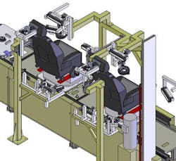
The assembly of car seats is based on a production-line process. After each left-and-right-side front passenger seat is fully assembled, it is placed onto a conveyor belt and moved down the conveyor, two at a time (see Fig. 1). To automatically inspect both sides simultaneously, IVS custom-built an imaging workcell that uses multiple cameras, PC-based frame grabbers, and lighting components, all linked over a programmable logic controller (PLC) to the supplier’s supervisory control-and-data-acquisition (SCADA) system. This acts as a large-scale distributed measurement and control system consisting of I/O hardware, PLCs, HMI, networks, and database systems used to transfer data regarding each specific seat type to the machine-vision system.
FIGURE 1. After each left-and-right-side front passenger seat is fully assembled, it is placed onto a conveyor belt and moved down the conveyor, two at a time. To automatically inspect both sides simultaneously, IVS custom-built an imaging workcell that uses multiple cameras, PC-based frame grabbers, and lighting components.
As pairs of seat subassemblies enter the imaging workcell, a proximity sensor interfaced to the system’s PLC triggers the presence of the part. Since the SCADA system is preprogrammed with the specific subassembly that should be present, it is used to open part-specific machine-vision check routines.
“For each pair of products,” says Waller, “40 individual checks are performed.” These include parts-presence tasks, part-type checks, and several gauging applications. While the parts-presence inspection software guarantees the correct placement of seatbelts, screws, under-seat and side handles, parts-type checking ensures that the correct fabric type, pattern, and color have been installed. Finally, gauging functions ensure that the handles used to both move the seat back and adjust the seat position are of the proper type.
“With a production cycle time of 80 s,” says Waller, “multiple cameras must be used to perform the inspection tasks. Because the seats must freely move through the imaging workcell, some of the cameras must be mounted on pneumatic gantries and moved within range of the seat subassemblies so that multiple inspections can be done successfully.”
Multiple cameras
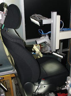
No fewer than 18 V10 CCIR cameras from NeuroCheck perform parts-presence, part-type, and gauging applications. “In essence,” says Waller, “nine cameras are used on each car-seat subassembly to perform these tasks. While seven cameras are positioned statically within the imaging workcell, two are mounted on pneumatic gantries and moved into position to inspect the head rest fabric and the fabric of the seat cushion” (see Fig. 2).
FIGURE 2. For each pair of products, 40 individual checks are performed. While seven cameras are positioned statically within the imaging workcell, two are mounted on pneumatic gantries and moved into position to inspect the head rest fabric.
Each of the seven cameras that are statically positioned performs a specific machine-vision job, such as inspecting for the presence of the seat’s track end clip, wavy metal washers, outer side shields, screw types, and passenger handles. Several 6-in. Monster white LED lights from Spectrum Illumination provide the correct illumination for these cameras.
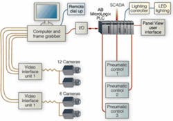
“As each subassembly enters the imaging workcell,” says Waller, “each of the LED lights is triggered from the system’s PC with an ME-8100A/B PCI-based 64-channel digital I/O board from Meilhaus that, in turn, interfaces to the system’s PLC and Spectrum Illumination lighting controllers (see Fig. 3). “In this way,” says Waller, “the lifetime of the LEDs can be extended, since they do not need to constantly illuminate the seat subassembly.”
FIGURE 3. As each subassembly enters the imaging workcell, LED lights are triggered from the system’s PC that, in turn, interfaces to the systems PLC and Spectrum Illumination lighting controllers. This PC also interfaces to the system’s 18 cameras.
Because so many cameras are used in the system, IVS developed a custom video interface board-essentially a multiplexer-and used two of the devices to multiplex CCIR data from each of the 18 cameras into five Sigma SLC PCI frame grabbers from Matrix Vision. “Using analog cameras instead of FireWire-, GigE-, or USB-based devices,” says Waller, “allowed us to reduce system cost while providing the necessary resolution required for this application.”
Fabric inspection
One of the most important tasks in the manufacture of car-seat assemblies is checking whether the correct fabric has been placed on both the car seat and the headrest. Since the placement of incorrect fabrics cannot easily be discerned by human operators, the system developed by IVS was also tasked with this function.
To properly inspect the fabric used in the assembly’s headrest, it was necessary to move the lighting to a position 5 mm from the fabric itself. Similarly, to inspect the car-seat fabric, the camera system had to move to approximately 6 in. (150 mm) from the fabric. This was done by mounting each camera and lighting system on 200- and 600-mm-stroke-length pneumatic cylinders, respectively. After the assembly enters the workcell, the cameras and lighting are moved into position, and the fabric on the headrest and car seat is illuminated. To light the headrest, a red on-axis ring light, type OARL from Metaphase was used, while for car-seat illumination, a Monster white LED light was selected.
“Selection of the correct lighting systems was crucial to system success, with the headrest presenting more of a lighting challenge due to the lack of pattern on the fabric,” says Waller. “However, the inspection task that must be performed on both images is relatively similar. Indeed, in all the inspection tasks, NeuroCheck software performed all the parts-presence, gauging, and fabric verification tasks.’’
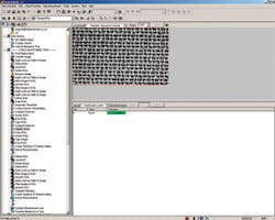
To perform fabric inspection of each headrest, for example, images of the fabric are first digitized into the system’s PC (see Fig. 4). After each individual image is digitized, a region of interest is applied to the image, which is then processed using a 9 × 9 erosion filter to enlarge the black objects within the image. This has the effect of increasing the intensity of the fabric’s weave.
FIGURE 4. Images of fabric are digitized and an ROI applied to the image, which is filtered to increase the intensity of the fabric’s weave. A Sobel edge detection creates horizontal white lines in the x direction of the image. After binarizing the resulting image and performing feature analysis, elongated objects in the x direction are highlighted.
Then, a Sobel edge-detection filter is used to create horizontal white lines in the x direction of the image. “By binarizing this resulting image and performing feature analysis in the resulting image,” says Waller, “elongated objects in the x direction are highlighted and displayed.” By performing a template match with this image the resulting region of interest can be resampled into a fixed input size for use with NeuroCheck’s Neural Network Classifier. The pattern is checked against a trained Neural Network algorithm that has been created from a series of patterns of all of the possible fabric types. The NeuroCheck Industrial Vision software then returns with a ‘Class Name’ match with a resulting percentage of certainty that can be evaluated against set acceptance levels. Using this technique, the NeuroCheck software can discern whether the correct fabric has been used in the headrest build.
Image processing
Performing these image-processing functions on different fabric types highlights the processes used to accomplish this task (see Fig. 5). The results of the image-processing operations and template match give a single dark image (middle right). When the same operations are performed on a different fabric type, the results of the image processing result in an image that is far from black and that more closely resembles a fabric weave pattern.
“Of course,” says Waller, “a number of different image-processing operations could have been used to produce a similar result. But by using NeuroCheck’s graphical user interface, it was relatively easy to select and program a series of machine-vision functions to perform all the tasks required of the system in a less-than-20-s cycle time. This sophisticated multidisciplined project was made easier by implementing a common-sense design philosophy, coupled with deployment of off-the-shelf vision-system peripherals, control systems, and robust industrial vision software, to fulfill both the customers and our own design expectations.”
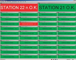
NeuroCheck was also used in the development of a user-friendly operator interface that displays the results of the 40 inspection tasks (see Fig. 6). Should any specific task, such as the presence of a track-end clip, fail, the specific function is highlighted in red. In such an event, the PC-based vision system transmits this information to the systems’ Allen Bradley Micrologix 11100 PLC. In turn, this actuates a set of pneumatically controlled cylinders that eject the assembly from the imaging workcell. After rework, the assembly can be placed back on the production line for a further final inspection.
null
