Clean Connections
Andrew Wilson, Editor
For developers of machine-vision systems, especially those used in industrial applications, reliability and mean time between failure (MTBF) is of utmost importance. While the types of cameras and frame grabbers or host interfaces used in machine-vision systems are important, so is the choice of cabling. In robotics-based applications in particular, where cables may be flexed a number of different ways during the life of the system, system developers must strive to obtain the highest-performance cable possible to ensure no loss or corruption of image data.
“If a cable has not been properly specified for automated machine-vision applications, the conductors can break and cause electrical shorts, which can cause costly downtime and damaged components,” says Don Nester, Chainflex product manager at igus. “Other failure modes include data errors, a reduction in transmission rates, and increased attenuation. Bit-rate error often occurs sporadically during operation and cannot be pinpointed after the unit is shutdown for repair.”
“Like a chain, a cable is as strong as its weakest link,” says Ron Folkeringa, business manager of Intercon 1. “Of equal importance is the fastening method of the cables’ connector to the camera or frame grabber/computer. Connectors with simple friction fits are grossly inadequate to ensure optimal signal integrity in a dynamic application. For that reason, screw fasteners are being used wherever there may be risk of cable or hardware movement.”
Ways and means
Responding to these demands, cable companies have developed a number of different ways and means to test their cables, offering system integrators reliability data based on in-house test methods. These test methods are generally proprietary to each individual machine-vision cable vendor; however, the results obtained can be used to judge the performance of a cable over long periods.
Whether the cables are for Camera Link, GigE, USB, FireWire, or other digital or analog standards, most cable companies perform a rolling flex test for their products. In this test, the cable is placed on or within a rolling track with a specific bending radius, traveling distance, and traveling speed.
Although different manufacturers use varied bending radii, traveling distances, and speeds, the result of such a test will only subject the cable to the effects of rolling the cable within specific parameters. Other effects that may occur during use include those of cable torsion, bending, and abrasion. In cleanroom environments, cables may also need to be tested for any particles that may be generated by the cable while in motion.
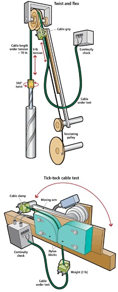
To account for these effects, cable companies subject their cables to more rigorous testing procedures. Northwire, for example, uses a rolling and torsional flex testing setup that stresses the cable by placing a 9-lb weight at one end, then pulls the cable 18 in. over a wheel and twists the cable by 360°.
The company also uses a bending flex setup that fixes one end of the cable stationary while a bending motion around a fixed object exists at another point in the cable length. Here again, a 2-lb weight is first hung to the cable while it is flexed 90° over a nylon block and backward 90° over another nylon block. This cycle is repeated every 2 s (see Fig. 1).
FIGURE 1. To account for torsion, bending, and abrasion effects, Northwire uses a rolling and torsional flex testing setup (above). The company also uses a bending flex setup that fixes one end of the cable stationary while a bending motion around a fixed object exists at another point in the cable length (below).
“In many cases,” says Folkeringa, “test data often omit the specifics of the test setup and parameters. Unless the test method is well defined and provided with the test results, an accurate comparison cannot be made. To that end, many equipment manufacturers realize that standard test methods may not be an adequate tool by which to determine cable performance for their specific application.
“These customers require the cable to be tested in test systems that the customer has created for the purpose of evaluating the durability of the entire machine they are developing,” adds Folkeringa. “Customers will spend months testing cables and other machine components in these test beds to ensure the cable and components will meet their performance requirements.”
While such tests may reveal the mechanical MTBF of a cable, they do little to reveal the electrical characteristics of the cable as such stress tests are placed upon it. To perform this analysis, it is necessary to electrically test the reliability and integrity of the data as it is transmitted from one end of the cable to another. One of the most common methods used to test the reliability of signal transmission is the bit-error rate test (BERT).
Data transmission
To perform a BERT on a cable assembly, a series of pseudo-random bits generated by a pattern generator is sent along the cable. For cable assemblies used in GigE camera-to-computer connections, this entails sending the pseudo-random data over the four twisted pairs of the GigE cable.
Once this series of bits is received at the other end of the cable, an error detector can be used to compare the received signal with the original. The bit-error rate can then be calculated as the number of bits received in error divided by the total number of bits transmitted. In nonpowered GigE systems, such a test gives the cable manufacturer flexibility since only two of the twisted pairs of the cable are used to transmit data.
After testing Ethernet cables, it may not matter whether the bit-error rates in two of the four twisted pairs are high since only two may be used to transmit data. Thus by terminating only those lines to a connector, data transmission errors will remain acceptable.
In power over Ethernet (PoE) systems, however, two of these twisted pairs are used to supply power to a device such as a camera. In poorly designed cables, transmitting power across the same cable as data can result in increased signal reflection and attenuation, ultimately resulting in a decrease in the signal-to-noise ratio (SNR) of the signal.
Of course, this holds true for other types of camera-to-frame grabber cables such as Camera Link where, for example, the Camera Link Base mode uses four twisted pairs to transmit data: one to transmit the clock signal and the remaining six differential pairs for camera control and serial communications between the frame grabber and camera. While such links are often required to work to better than one error in a terabit (1012), the need for reliable data transmission in camera control and serial communication may not be as stringent, allowing cable manufacturers to reassign different differential pairs to their connector pins.
“Because of the requirement of such links to transmit less than one error in a terabit of data, it takes about three and a half minutes to transmit a terabit of data on an eight-pair Camera Link cable clocked at 85 MHz. To collect a statistically significant number of samples, some experts recommend up to 100 repetitions. This would require over 350 minutes to completely test the cable using traditional bit-error-rate testing methods,” says Daniel Cronch, product development specialist at 3M Electronics, Electronic Solutions Division.
Components Express Inc. (CEI) has elected to develop a BERT for Camera Link cables to certify every cable the company produces. The BERT can quickly certify all production cables in seconds as opposed to an eye pattern test, which takes hours and can only be used effectively on a small sample of a production run. The BERT also allows testing of all pairs on the Camera Link cable simultaneously; eye pattern tests only allow testing of one pair at a time. All modes of Camera Link may be tested in this fashion to certify cables at Base, Full, and 80-bit modes.
“It is critical for customers to use the performance charts generated to compare the pixel clock of their system and the mode in which their camera will operate,” says Ray Berst, president of CEI. “Flex testing is incorporated with the BERT test to show degradation over a number of cycles.
“Typically cables exhibit an initial performance loss (over the first 500,000 flex cycles) and then stabilize for millions of flexes until they finally fail. Therefore, it is crucial to have abundant headroom for cables in a flex environment to ensure the cable performance is adequate for a system that incorporates mechanical movement of the cable assembly,” Berst says.
Signal integrity
While the BERT is a fast method of providing information about whether a correct sequence of bits has been transmitted over the cable, it provides little information about the integrity of the transmitted signals themselves. Because of this, some cable vendors use the time-tested approach of measuring the received signal in the time domain using an oscilloscope or more often a signal analyzer to generate an eye diagram for measuring parameters including distortion, noise, timing error, and jitter.
To generate an eye pattern, a signal generator is once again used to generate a series of signals along each of the twisted pairs of the cable. To test cables used in camera-to-computer connections, the clock frequency of the camera or frame grabber can be generated by the frequency generator. When the received data pattern waveforms are superimposed, this generates the eye diagram. Unlike the BERT, which determines whether the correct sequence of bits has been transmitted, generating an eye pattern requires that samples of data are taken at a rate that is often below that of the data rate that will eventually be transmitted when the cable is deployed.
In Gigabit Ethernet, for example, final data transmission rates may be 1 Gbyte/s. To fully sample this would require an instrument capable of sampling at data rates of 20 Gbits/s. While test equipment is available from companies such as Tektronix and others, digital sampling oscilloscopes are relatively expensive, costing on the order of $20,000. More important, however, the time-domain signal analysis of the recovered signal is only a sample of the data transmitted. Should infrequent events occur, the eye diagram may not reveal these events depending on the sampling rate used.
“Like the BERT,” says 3M’s Cronch, “one could generate an eye diagram by fully sampling terabits of data for a long period of time. More often than not, a smaller representative sample of the data is collected. The data is presented as an eye diagram with a mask or ‘keep out’ area. The eye diagram can be considered analogous to a statistical bell curve. Defining the eye mask is similar to setting the spec limits on the bell curve. Thus, the eye diagram may not sample every infrequent event but uses the probability distribution to predict such events occurring.”
Despite this, sampling can provide information about signal degradation not found in the BERT. These are displayed in an eye diagram. This eye pattern is named so because the digital data initially transmitted as a series of square pulses of ones and zeros in the shape of a top hat or straight line will degrade into a Gaussian shape after being received at the transmitter. While a perfect eye diagram would then be of a perfectly formed rectangular shape, in reality the reconstructed waveform resembles an eye. From this eye diagram, parameters such as distortion, noise, timing error, and signal jitter can be measured.
Signal attenuation and interference increase with the distance of the cable; at a certain cable length the SNR will become unacceptable. As this cable distance increases, the region within the eye will become smaller and will encroach onto the mask area of the eye diagram. This mask can be set to describe a specific voltage range (on the y axis) across a specific time period (on the x axis).
In this way, the developer can set specific levels and see the effects of signal amplitude changes, distortion, timing error, and jitter across a number of different cable lengths and designs. As cable length increases, signal attenuation will reduce the aperture of the eye in the vertical direction while an increase in capacitance and return loss will decrease the rise and fall slopes of the eye.
Eyes closed
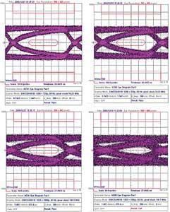
To highlight the effects of this, Belden has compared its HDMI cable against a Chinese cable used in the company’s BJC Series-2. Using a 74.25-MHz clock on a 50-ft cable, the Chinese cable passes the eye test at 74.25 MHz at 50 ft, but the traces of the rise and fall start to encroach on the eye mask. If the cable is made longer or the bit rate increases, the cable would not pass the eye pattern test.
The Belden cable’s eye diagram does not encroach the eye mask by as much and could be made longer. Using an increased bit rate for the same 50-ft cables, at 1080p (148.5 MHz), the 50-ft Belden cable just passes the eye pattern test, but the Chinese cable fails (see Fig. 2).
FIGURE 2. To highlight the effects of signal attenuation, Belden has compared its HDMI cable against a Chinese cable used in the company’s BJC Series-2 (top). The Chinese cable passes the eye test at 74.25 MHz at 50 ft, but the traces of the rise and fall start to encroach on the eye mask. Using an increased bit rate for the same 50-ft cables, at 1080p (148.5 MHz), the 50-ft Belden cable just passes the eye pattern test, but the Chinese cable fails (bottom).
To engineer the highest-performance cables, different types of materials and configurations of cables are used within the cable shroud. But the maximum length, data rate, and signal integrity obtained do not merely depend on the cable’s materials and construction quality—they can also depend on whether any active electronics are placed in the path of the cabling itself.
CEI, for example, recently developed a line of Camera Link cables that integrates pre-emphasis into the Camera Link cable. This allows CEI to offer Base Camera Link cables running at 85 MHz to extend as far as 25 m and Full Camera Link cables also running at 85 MHz to extend as far as 17 m with no signal degradation (see “Pre-emphasis increases Camera Link cable distances,” Vision Systems Design, January 2009).
In choosing a cable for a camera-to-computer connection, system integrators must be aware that the choice of cables is just as important if not more so than the camera or frame grabber. While comparing manufacturers’ data in the form of the BERT and eye diagram charts is useful, the data must be weighed in terms of the system to which the cable will be deployed. For high-speed, point-to point interfaces such as Camera Link, transmitted data, once degraded, is not retransmitted. Because Camera Link is used in high-speed systems, data integrity is of high importance. In slower FireWire systems, data packet resends can often compensate for the lack of a high-quality cable; however, resending packets can result in lower system performance.
“Fortunately,” says Folkeringa, “the new revised appendix D of the Camera Link standard will require cable manufacturers to meet defined electrical performance requirements for their cable to be registered as a Camera Link product. This will be a significant improvement over the current revision, which defined the construction of a cable rather than the electrical performance (signal integrity) of the cable.”
Company Info
3M, Austin, TX, USA
www.3m.com/machinevision
Belden, St. Louis, MO, USA
www.belden.com
Components Express Inc.
Woodridge, IL, USA
www.componentsexpress.com
igus, East Providence, RI, USA
www.igus.com
Intercon 1, Baxter, MN, USA
www.intercon-1.com
Northwire, Osceola, WI, USA
www.northwire.com
Technical Cable Concepts
Costa Mesa, CA, USA
www.techcable.com
Tektronix, Beaverton, OR, USA www.tek.com


