MEASUREMENT & GAUGING: Lens test system uses dual USB cameras
In lens manufacturing, glass blanks are first ground and polished to form specific shapes and surfaces of individual lenses. During this process, centering errors may occur in which the mechanical axis and the optical axis of the lens are not concurrent. Precise knowledge of these centering errors is important since they will have direct impact on the imaging quality of an optical assembly or subassembly.
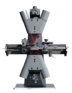
International standard ISO 10110 defines the centering error of a single optical lens as the surface tilt angle between the normal to its spherical surface and the symmetry axis of the cylindrical edge of the optical element. By using optical centering testers such as the VP 30508 from Schneider-Kreuznach (Bad Kreuznach; Germany; www.schneiderkreuznach.com), operators can measure these centering errors and decide, whether or not to use these lenses in an optical assembly.
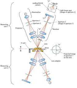
Before any lens measurements can be made, however, systems must be calibrated at the factory to ensure that the readings are correct. To perform this task, a surface mirror is mounted in a special calibration tool and placed underneath the measuring head. The calibration tool consists of a micrometer screw and a lever mechanism that transfers the micrometer displacement into an angular displacement of the surface mirror, This leads to a displacement of the light spot reflected from the mirror onto the camera system (see Fig. 1).
To measure lens centering errors, a lens is then placed on a lens adapter. To illuminate the lens, a light source is collimated through an aperture and focused on the reflecting surface of the test piece. The reflected light beam is then again collimated through an aperture where the light is captured by an image sensor.
As the lens rotates under control of a PC-based drive mechanism, the reflected light spot is measured by a board-level 1024 × 768-pixel mvBlueFOX-M USB 2.0 camera from Matrix Vision (Oppenweiler, Germany; www.matrix-vision.com). After the image is transferred to and captured by a host PC the system software calculates the centering error from the deflection of the reflected light spot.
Edge thickness difference or edge thickness variation is not necessarily an indication or a manifestation of a centering error. If, however, the lens is not perfectly round (for example, due to run out), this will correspond to a measurable centering error when the lens is rotated.
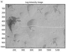
Any centering error can be observed in the camera image as a deviation of the energy centroid. In lens elements, this centroid will follow a more or less circular trajectory while the lens element is rotating. The diameter of this circular trajectory then provides a measure of the centering error.
If a centering error exists on the surface of the test piece compared to the rotation axis of the lens, the light spot will move on the camera sensor (see Fig. 2). By analyzing the images taken by the camera during a complete rotation of the lens element, the maximum deviation of the energy centroid in x and y direction can be computed by the software and displayed as a red bar chart (“Total”). The larger of the two values indicates the centering error once the lens has completed a full rotation.
Alternatively, the diameter of a circle fitted to the trajectory can be displayed (lower right) to represent the centering error if the trajectory is almost circular in shape. A bar chart also indicates how well the camera is focused on the surface of the lens under test.
If the centering error is within tolerance, the measured value is documented and the lens element can be used in production. If the centering error is out of specification, the measured lens element will either be discarded (if it is an inexpensive lens element) or it can be re-machined in a centering machine (if the lens element is more expensive).
FIGURE 3. By overlaying the image taken by the camera with a software-generated trajectory of the measuring spot path (in red) using more than 1000 measurements, the maximum deviation of the energy centroid in x and y directions can be computed.
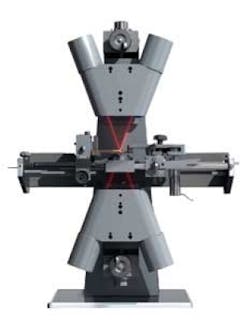
Because the instrument is equipped with both an upper and a lower optical head, single lens elements with two surface tilt angles can be measured from both sides. Since knowledge of the focal length or radius of curvature of the lens surfaces is not needed, there is no need to swap relay lenses when testing different lens types.


