As technology advances, there is a push to use machine vision in more new applications. Most of these applications belong in the traditional machine vision space. But some do not—and these applications have wildly differing requirements compared to conventional machine vision implementations. When working with applications in non-traditional areas, one tends to run into problems as the imaging system has to adapt to different environmental conditions in terms of pressure, temperature, and shock and vibration.
Unmanned aerial vehicle (UAV) imaging applications, specifically, are on the rise. With advances in drone technology, imaging technology also must advance to provide the same consistent imaging performance that one would expect to see in more conventional machine vision applications.
This article looks at the growing number of machine vision applications enabled by advancing UAV technology, the inherent problems that arise from imaging in these varying and often harsh environments, and how these problems are being solved.
Importance of Imaging for UAVs
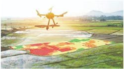
UAV technology and imaging have always been closely linked. Even early commercially available drones came with an imaging system (Figure 1).
The need for imaging in UAVs is fairly obvious, as the need for direction and guidance requires the ability to see where that drone is positioned. Barring the use of radar, the only way to determine the position of the UAV is to find out what it is seeing. However, the need for imaging on UAVs goes beyond simple direction and movement. Many applications aboard drones use a vision system to image large swaths of land—not to know where to navigate to next but rather assess the environment to obtain a variety of useful types of data.
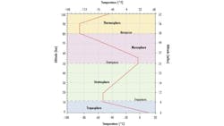
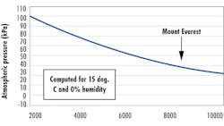
Aerial photogrammetry, for example, is an application that uses 2D imaging by camera systems onboard UAVs to map 3D areas on the ground. Ground sample distance (GSD), the altitude at which aerial photogrammetry takes place, is related to the Nyquist frequency of the imaging system and the sample being imaged.1 Therefore, a high performing imaging system allows the UAV to go higher in altitude, which results in a wider field of view and, subsequently, a need for fewer photos to be taken. Current military drone technology allows drones to fly up to 50,000 ft, or 15.2 km, which presents a lot of challenges for the imaging system.2 Temperature and pressure vary between ~30˚C to -50˚C and 100kPa to ~20kPa, respectively (Figure 2).
As temperature and pressure make elements in the lens vary and shift, imaging across such a broad range becomes very difficult, making the imaging system the limiting factor for this application. Finding ways to improve the imaging capabilities of the machine vision system is of particular importance for this application to continue advancing the capabilities of aerial photogrammetry.3 (Figure 3)
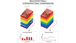
Another important application in the UAV imaging space is the multi- and hyperspectral imaging of vegetation. Multispectral imaging involves gathering data in multiple separate wavelength regions, while hyperspectral imaging involves gathering data over a single, large, continuous range of wavelengths. The concepts involved in imaging vegetation from a UAV are similar to photogrammetry in that altitude affects the imaging system significantly,4 but this kind of imaging adds an important dependence on wavelength, which further complicates the problem. Instead of having to design a system that works across a broad range of temperatures and pressures, an already difficult task, there is the additional need to design systems that operate across a broad wavelength range while still having a high spectral resolution. The spectral resolution of a system relates to the smallest size of wavebands the system can distinguish. Multispectral imaging has lower spectral resolution than hyperspectral imaging but is much easier to design and tends to be less expensive. (Figure 4)
The type of spectral imaging needed varies between applications. A lot of vegetation types will show wildly different properties at specific wavelengths, most of which are not in the visible spectrum. This makes having small, discrete spectral bands in multispectral imaging very useful for gathering the most information from the 2D UAV images. Therefore, having a system that performs with both a high spectral resolution and a high imaging resolution is ideal for these applications.
While the above mentioned are very common imaging applications, the rapid advances made in UAV technology and imaging technology are enabling a range of different applications to flourish in both the military and commercial spaces. In military operations, UAV applications in target decoys, general combat missions, and surveillance allow for a reduction of losses and access to more important, time-sensitive operations. In the commercial space, UAVs are transforming disaster relief, archeology, and mining by utilizing similar concepts as photogrammetry and environmental imaging to reduce time and labor.
Improving Lens Performance in UAV Applications
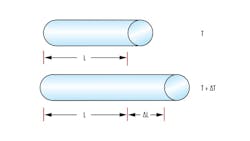
As mentioned above, the altitude at which UAVs fly brings about a plethora of harsh environments, all of which will affect the performance of a lens. In order to optimize the above-mentioned applications, designing high-performance imaging systems is necessary but is difficult in such varying conditions. Changing temperature induces shifts in the physical size of objects due to a concept called the coefficient of thermal expansion (CTE). (Figure 5)
The amount at which objects and materials shift depends on this coefficient, which differs between materials. Glass and metal have different CTEs, which introduces significant potential for elements in an imaging lens to shift, as well as introduces tilt or general misalignment when heated or cooled. This then introduces aberrations and reduces imaging performance, which is detrimental to UAV imaging applications. The refractive index of the lens also shifts with temperature, but the effects of this phenomenon impact system performance less than the changing of physical size due to thermal expansion. The goal, then, is to reduce shifting in the elements of the lens assembly so as to reduce the sensitivity of the lenses to misalignment.
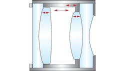
The first problem, lens misalignment, is fixed mostly through rigorous lens design. To maintain performance across the temperature range, the elements are designed so that when they shift, other elements in the lens compensate for the growth or shrinking (Figure 6).
This design is more rigorous and time consuming, but it is the only way to keep steady performance across a temperature range. This also generally leads to designs with fewer elements. The balance between a low element design and a high-performing design is complex, but not impossible, to figure out. It should be noted that there is also commonly a flexure inserted into the design, which relieves pressure from the thermal growth on the contact points between the metal and glass elements.
It is also important to design a lens that is not sensitive to shifts in movements between the elements. This is a fairly common process done in lens design as tolerancing revolves around the same concepts, but adding the shifting inherent to temperature changes on top of tolerancing complicates lens design further. To make lenses less sensitive, lens designers tend to look at ways to reduce phenomena that would introduce significant aberrations into a system. This is often done by carefully controlling lens radii of curvature, glass types, spacing and thicknesses in the imaging assembly. The combined effects of temperature-dependent spatial shifts and tolerancing shifts make designing an insensitive lens more difficult, but a careful lens designer balances this using the above-mentioned techniques.
A lens can also be designed to compensate for changes in pressure related to altitude changes. One should accurately model the air inside and outside of the lens, at different pressure values, in lens design software to accurately predict the effects this has on the lens, then design a lens that can tolerate these shifts.
Designing Lenses to Withstand Extreme Shock and Vibration
While temperature, pressure, and how to mitigate their effects on lenses are important factors in allowing a lens to be useful in UAV applications, there are other types of ruggedization that can be added to a lens to make it more suited for the altitude changes inherent in UAV imaging. For example, quick acceleration changes inherent in drone flying require shock and vibration ruggedization. This allows the elements in an imaging lens to stay fairly stable when undergoing high shock. This is done by simplifying optomechanics and introducing glue around single element lenses in order to avoid shifting in the lens barrel and causing misalignment.
Another factor to consider in UAV applications is ingress protection. Ingress refers to the presence of unwanted particulates, such as water or dust, in the imaging application. Dust and water will reduce the imaging performance of a lens as light hits these particulates and gets redirected in unpredictable ways. This can be mitigated by sealing the elements inside the lens barrel from the outside world. One can also replace the air inside a lens with an inert gas during assembly, which will remove existing particulates and prevent other particulates from the outside to reach the inside of the lens.
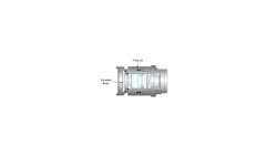
This is especially helpful for UAV applications, as a big problem with thermal fluctuation is condensation on lenses. When humidity exists in the lens, water particles can easily adhere to the lens, which redirects the light rays hitting that lens. This severely reduces imaging performance and is one of the main problems for imaging applications at low temperatures. As Figure 7 shows, this condensation can be further mitigated with a hydrophobic window on the front element.
In addition to the complications previously outlined, an important consideration involved in UAV imaging is weight. Lenses designed for imaging at high elevations must be light so they do not hinder the UAV’s ability to fly effectively. Though one would think this would complicate the design for a UAV imaging lens, it actually aids in simplifying the design. A lighter lens tends to have fewer elements and complex optomechanical components.
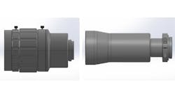
Simplifying optomechanics is already a common practice in designing these types of lenses, as the thermal compensation needed with too many elements and complex optomechanical design becomes problematic for lens designers. (Figure 8)
Although putting machine vision systems into a broader range of applications with harsher environments such as UAV imaging seems daunting, the imaging world has adopted several useful design paradigms and tricks in order to accommodate this. One of the biggest spaces in which this can be seen is the UAV imaging application space, where altitude changes bring about an assortment of different conditions that can affect the performance of imaging systems negatively. Temperature changes, pressure changes, shock and vibration, and humidity all pose problems at high and varying altitudes for imaging systems. Figuring out how to reduce the effect that these have on UAV imaging systems allows UAV applications to be more efficient and diverse in their tasks. Given the push for further advancement in UAV technology, it is important for imaging systems to keep up in order to match the capabilities of the mechanical components in UAV systems.
References
1. Wawrzyn, D. What is Ground Sample Distance and How Does it Affect Your Drone Data? Propeller. August 2023. https://www.propelleraero.com/blog/ground-sample-distance-gsd-calculate-drone-data/
2. Leslie, J. How High Can a Drone Fly? Drone Survey Services. 2023. https://dronesurveyservices.com/can-you-fly-a-drone-in-a-public-park-in-the-uk/
3. Pidwirny, M. Laboratory 2: Heat and Temperature in the Atmosphere. Pressbooks. April 5, 2021. https://pressbooks.bccampus.ca/physgeoglabmanual1/chapter/lab2/
4. Miller, C. Human Responses to High Altitude. Pressbooks. April 15, 2021. https://humanbiology.pressbooks.tru.ca/chapter/8-8-human-responses-to-high-altitude/
About the Author

Florian Gollier
Florian Gollier is an optical systems engineer at Edmund Optics (Barrington, NJ, USA) where he guides customers through the process of designing machine vision solutions for their applications. He holds a master's degree in optical sciences from the University of Arizona, a master's degree in material design and innovation from the University of Buffalo, and a bachelor's degree in engineering physics from the University of Buffalo.
