High-speed cameras help validate store separation prediction models
Photogrammetric high-speed camera missions capture six-degree-of-freedom motion data that enable completion of airborne certification programs.
Russell Moore
An accurate prediction of the trajectory of a store released from an aircraft is critical in assessing whether the store can be released safely as well as if it will accurately reach its target. The high-speed cameras used for acquiring data that characterizes aircraft performance and avionics/equipment must be designed to perform optimally, accurately and reliably in harsh conditions, due to the high cost of keeping a test platform in the air.
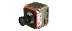
Figure 1: The nHSC-31-S1 camera is a standalone and/or networked high-speed camera that is capable of 500 fps operation at full resolution, and includes an integrated CompactFlash recorder to allow easy removal of critical post-test data.
For manned aircraft and UAVs, a number of airborne applications including stores separation, missile deployment, and landing gear analysis, requires Flight Test Instrumentation (FTI). For these types of FTI applications, the photogrammatic data is captured in order to characterize the performance of the aircraft, the platform’s avionics, and the performance of other equipment (Figure 2).
FTI typically involves the use of compact, lightweight, and rugged high-speed cameras capable of capturing moving images with exposure times for each image of less than 1/1,000 second or frame rates in excess of 200 frames per second (fps). Such cameras primarily record fast-moving objects as digital images onto a storage medium.
After recording, the images can be played back in slow motion to examine the motion for scientific study of transient phenomena. Early high-speed cameras used film to record high-speed events, but have been superseded in recent years by entirely electronic devices. These modern cameras use either a CCD or a CMOS active pixel sensor that typically records over 400 frames per second onto DRAM.
The system level solution
When used with motion analysis software, high-speed cameras provide FTI engineers with the ability to conduct in-depth, quantitative analysis of the acquired high-speed images. Software solutions such as TEMA TrackEye software from Image Systems (Linköping, Sweden; www.imagesystems.se) supports automatic tracking of up to three targets and calculates for velocity and acceleration.
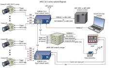
High-speed cameras can be combined with other elements to provide an integrated FTI system solution for photogrammatic analysis of store separation (Figure 3). In addition to the camera, a complete system would typically include a network-based camera manager unit, a managed network “core” Ethernet switch, additional network switches, a networked data recorder, and a multifunction camera control panel unit. The core switch serves as a network fabric for passing message packets from cameras or other sensors located around the aircraft. The switch packetizes and time-stamps the video or camera images. To ensure accurate time-stamping, the FTI system provides a grand master clock. If older PCM networks are present on the test aircraft, the PCM data can be converted into modern Ethernet packets via gateway devices on the FTI system.
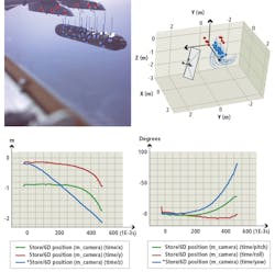
Figure 2: During a typical stores release, as the target object falls from the aircraft, its image is recorded on a frame every 0.005 seconds. Since the camera axis orientation and the target’s image position in the image sensor plane is known, Snell’s law and compensations for known lens distortion can be applied. This enables a vector to be established from the image sensor plane through the lens to the target. If two or more cameras of known position have vectors from their image sensor plane to the same target at the same instant in time, triangulation can be used to determine the target’s position in the aircraft coordinate system.
In advance of the test flight, the FTI network engineer programs the cameras and sensors to assign triggering events and determine where in the FTI system to transfer the resulting data packets. Use of an Ethernet-based camera manager, which resides on the network, simplifies the orchestration of all of the triggering events. The resulting image data is first stored on the camera itself. It can also be archived by sending it to a network recorder or transferred to discrete memory residing in the camera itself. Because every image frame is time-stamped, either by the FTI data acquisition unit or by the high-speed camera, it’s possible to accurately combine and synchronize all of the acquired data after a test flight or mission.
Prediction model validation
One typical FTI application for which high-speed cameras are essential is for conducting photogrammetric studies to validate performance prediction models. In FTI, photogrammetric techniques involve obtaining measurements from individual digital images to analyze the precise position and orientation of objects in three-dimensional space during a test flight. In many cases, wind tunnel experiments will be performed in advance to generate the prediction model, which helps to minimize program risk.
An example of how photogrammetric missions are used in FTI is provided by store separation testing. Validation of state-of-the-art store separation prediction techniques is required to complete FTI studies for airborne certification programs. The use of photogrammetric high-speed camera missions enables the validation of the store separation prediction model by capturing six-degree-of-freedom motion data. The FTI engineer correlates the quantitative data from the separation testing with the actual flight test results to validate the models. This data is measured when the stores are within a defined volume of analysis while on the test vehicle. Typically, flight clearance authorities request measurement accuracy on the order of a few inches for proper correlation.
For example, when a missile is jettisoned from an aircraft in flight, photogrammetric triangulation techniques are used to quantify the missile’s spatial position and orientation. This enables the weapon’s displacement and attitude to be quantified after it has been released or launched from the aircraft. Such information is typically used to validate the accuracy of a prediction or to determine if the characteristics are “safe” enough to proceed to more severe release conditions.
The calibration process
To accomplish this type of photogrammetric analysis, several calibrations of the test equipment must be performed to quantify details such as the camera location and any lens aberrations. The goal is to ensure that the high-speed cameras are operating at 200 frames per second with exposures operating at 0.005 seconds per frame. The lens calibration process simply maps out any distortion in the lens, such as pin-cushion or barrel distortion, and determines how the projection of the object’s image onto the camera’s global shutter CMOS image sensor is affected. Lens calibrations are performed by aiming the camera at a calibrated target.
Figure 3: High-speed cameras can be combined with other elements to provide an integrated Flight Test Instrumentation system solution for photogrammatic analysis of store separation. In addition to the camera, a complete system would typically include a network-based camera manager unit, a managed network “core” Ethernet switch, additional network switches, a networked data recorder, and a multifunction camera control panel unit. The core switch serves as a network fabric for passing message packets from cameras or other sensors located around the aircraft. The switch packetizes and time-stamps the video or camera images.
In addition to calibrating the lens, the test objects, in this case the aircraft and stores, also have to be “targeted.” Targets are easily identified points (either integral to the object or placed on the object) at known positions with respect to a coordinate system. The coordinate system for the aircraft is the standard coordinate system, including water line, butt line, and fuselage station. While only three targets are required for a photogrammetric solution, many targets are usually affixed to ensure that the minimum number will be available. It is imperative that the targets be visible by as many cameras as possible.
In addition to fixing the position of the camera’s image sensor plane, an initial orientation of the camera must also be obtained. This orientation (the direction the camera is pointed with respect to the axes of the aircraft) will be used as initialization data in an iterative computer algorithm to determine precise camera orientation for photogrammetric analysis.
Camera synchronization
Using a precise, common time reference such as the IRIG (Inter-Range Instrumentation Group) or IEEE-1588 PTP protocols allows cameras and other devices to synchronize their time base to within a few hundred nanoseconds. Synchronizing system components to a common time base enables simplified system designs and simplifies wiring – especially important for minimizing size, weight and power requirements (SWaP) on test aircraft.
During a typical stores release, as the target object falls from the aircraft, its image is recorded on a frame every 0.005 seconds. Since the camera axis orientation and the target’s image position in the image sensor plane is known, Snell’s law and compensations for known lens distortion can be applied. This enables a vector to be established from the image sensor plane through the lens to the target. If two or more cameras of known position have vectors from their image sensor plane to the same target at the same instant in time, triangulation can be used to determine the target’s position in the aircraft coordinate system.
An example of a high-speed camera designed for FTI is the recently introduced nHSC-36-S1-1 miniature camera from Curtiss-Wright Corp. (Ashburn, VA, USA; www.curtisswrightds.com). Designed to capture high-speed imagery and record data in the harsh environments and rugged conditions of aerospace test applications, this camera supports the high resolution (1280 x 1024 pixels) required for use in demanding airborne store separation testing and helicopter testing applications (Figure 1). Optimized for SWaP, the camera measures 3.12” W x 3.42” H x 2.87” L, weighs 50 oz., and supports 100/1000BASE-T Ethernet to achieve greater than 25 MBps image data download rates.
Russell Moore, Curtiss-Wright Defense Solutions, Aerospace Instrumentation (Ashburn, VA, USA; www.curtisswrightds.com)


