Vision system verifies part orientation before adhesive application
In automotive manufacturing, replacing welding with adhesives helps engineers design lighter and, in some cases, stronger assemblies. Fenders, side panels, and housings that must be joined to the main body or other parts of the vehicle with adhesives require accurate adhesive application to ensure parts and assemblies function as intended.
The adhesive application station at Geely Auto (Hangzhou, China; www.geely.com) is a case in point. Improperly placed or oriented parts loaded into the station may result in waste, premature part failure, or lead to a robotic adhesive applicator colliding with parts on the tray, leading to shutdowns. Loading of parts into the tray is always manual, but previously, parts were checked manually using a gauge, which was time consuming and error prone. It’s challenging for a human to detect part placement within 0.5 mm and angles less than 1° and if a manufacturer seeks to report on the position of up to 20 parts in one minute, manual inspection becomes impossible.
That’s why Geely enlisted Bluewrist Inc. (Markham, ON, Canada; www.bluewrist.com) to develop a faster and more accurate method for automating part orientation in its adhesive application process.
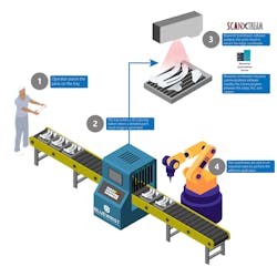
Determining the correct orientation of up to 40 different types of automotive parts requires five separate lines, with each line accommodating five to eight different parts. Each batch of parts placed in a 1 x 2 m tray passes an SR-1000 vision sensor from Keyence (Osaka, Japan; www.keyence.com), which identifies a unique barcode for each tray to determine which batch combination of parts is being inspected by the system. Bluewrist software running on an industrial computer holds pre-loaded tray information, allowing the operator to understand which parts should be in the tray.
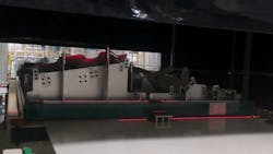
Once the vision sensor scans the barcode, the tray moves into a tunnel where two MLWL223 weCat3D 3D profile sensors from Wenglor (Tettnang, Germany; www.wenglor.com) scan the tray and the parts inside from overhead as the tray moves along a conveyor (Figure 1). MLWL223 sensors feature a Z working range of 300 to 1000 mm, a Z measuring range of 700 mm, an X measuring range of 280 to 830 mm, and a 660 nm red laser light source. Bluewrist’s scanXtream software performs 3D point cloud processing, feature extraction, and 3D alignment in a few hundred milliseconds and confirms part location and orientation in under five seconds, according to Jay Lu, Director of Engineering, Bluewrist.
“These are large trays, so we are dealing with a lot of 3D data all at once. Without optimized software, the process would take too long for an in-line system,” he says. “In scanning and processing up to 20 parts in offline software, it could take a few minutes to extract all that information. We have to extract everything in seconds.”
After generating a point cloud, the software identifies every part and determines its position. If a part is misplaced or not present, or if the robot cannot otherwise apply the adhesive bead, an alarm sounds for this part, and a notification pops up on the HMI for the operator, indicating which part has a placement issue.
If all the parts fall within the placement tolerance, the part’s XYZWPR pose is sent to a Fanuc (Oshino, Japan; www.fanuc.com) robot via TCP/IP and a programmable logic controller (PLC) from Siemens (Munich, Germany; www.siemens.com) for adhesive application (Figure 2).
Flexibility and customization represent additional advantages of scanXtream software, according to Lu.
“Geely has many models, so its factory lines are flexible by nature,” he says. “With the software, they can easily reprogram the line with new or different parts as required, and we can help them make these updates within the software instead of them having to start the process over from scratch.”
SPCWorks in-line dimensional data control and reporting software from Bluewrist also enables Geely to track the history and data of individual parts, which allows the operator to update the process to include load and unload procedure data.
This software collects and reports dimensional data from the machine vision system and generates reports that can be used by team members to monitor and access the process stability to predict and prevent defects or issues, according to the company.
About the Author

James Carroll
Former VSD Editor James Carroll joined the team 2013. Carroll covered machine vision and imaging from numerous angles, including application stories, industry news, market updates, and new products. In addition to writing and editing articles, Carroll managed the Innovators Awards program and webcasts.

