Machine vision battery tray inspection system uses 3D scanning
An electric vehicle requires a functional battery just as a traditional automobile requires a functioning gasoline tank. If the battery fails for whatever reason, the electric vehicle dies on the road. Ensuring that the battery’s tray can handle the thermal expansion of the battery pack and withstand shock and vibration while the vehicle moves is of paramount importance.
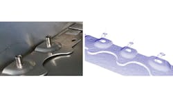
An 80 kg, 4 m long, and 1.5 m wide battery tray currently in production by a major automobile manufacturer, designed for a high-performance electric sedan with the ability to travel long ranges before recharging, requires over 500 rivets and over 100 welds for proper assembly. More than 65,000 battery trays annually will roll off the production line. In order to maintain this pace, inspection of over 680 features on the battery tray including welds, rivets (Figure 1), holes, clinch nuts, and mounts must take 140 seconds or less to complete.
Robot and vision solution company Bluewrist (Markham, Ontario, Canada; www.bluewrist.com) developed a battery tray inspection machine consisting of a pair of 3D laser profilers, each mounted onto a robot arm, capable of completing the required inspection routine within the required cycle time, according to Jay Lu, Director of Engineering, Bluewrist.
The manufacturer had prior experience with vision system-based inspection and understood the necessity of designing a system to inspect the battery trays before the vehicle went into production, according to Nathan Joiner, Business Development Manager at Bluewrist, who worked on the project.
Related: Understanding the latest in high-speed 3D imaging: Part one
Bluewrist’s hardware agnostic proprietary inspection software, ScanXtream, can accommodate most brands of robot, sensors, and PLCs required by a client, according to Joiner. FANUC (Oshino, Yamanashi, Japan; www.fanucamerica.com) M-710iC robots, were selected by the customer for use with the vision system as FANUC-model robots were already in use at the manufacturing plant.
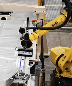
A Keyence (Osaka, Japan; www.keyence.com) 3D laser profiler mounts onto each robot arm (Figure 2). The manufacturer requested the use of Keyence hardware and Bluewrist chose the LJ-V7300 model. The 240 mm field of view (FOV) requirement for the application served as the chief determinant in the selection of this particular model. According to Joiner, the next model down from the LJ-V7300 in that series has a fairly significant, almost one-third drop in FOV that would make impossible completing the inspection within the required cycle time.
The laser profilers use a working range of just under 300 mm for this application and calibrate using a scanner/robot TCP software tool that takes around ten minutes to complete.
The need to use a Keyence controller to export 3D point clouds into ScanXtream provided a challenge for using Keyence laser profilers. The company has a unique data packaging methodology that can require special drivers to make sure image data moves smoothly between their controller and ScanXtream, says Lu. Bluewrist collaborates with Keyence to develop those drivers as needed.
Related: Understanding the latest in high-speed 3D imaging: Part two
The battery tray passes through two work cells for spot welding, clinch pinning, riveting, drilling, and mid-welding prior to loading onto a trolley and delivery to the inspection station for manual loading into a fixture that features 180° rotation. Inspection cycle time allots 20 seconds for tray loading and unloading.
The manufacturer guarantees a +/- 0.5 mm position variation on X, Y, or Z axes for the mounted battery tray. The vision system has much wider variation tolerance, up to +/- 5 mm on any axis, because the 3D laser profilers are mounted on robots, says Lu.
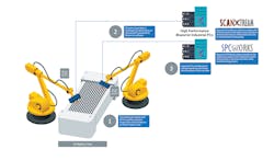
With the battery tray in position, an operator clicks a start button on an HMI to begin the automated inspection sequence. The laser profilers make separate scans over the battery tray for three categories of inspection: welds, then rivets, and then all remaining features, such as holes, mounts, and slots, captured together. The robots require around 30 total passes each to gather all the necessary data (Figure 3).
Welds are inspected for width and length tolerances, and rivets are inspected for flatness tolerance. For other all features the manufacturer requested that the vision system check only for presence, in order to keep the inspection cycle time within 140 seconds.
Processing speed, a common challenge for weld inspection, challenged Bluewrist in this application. The company had not previously developed a system to scan and process so many welds, more than 100, in such a short cycle time.
Bluewrist has extensive experience with complex and multi-camera inspection applications, says Lu, and has a solid grasp of how much data a single CPU can process in a given amount of time. For this application, based on prior experience, the company knew that each laser profiler required its own dedicated high-performance PC (Figure 4).
The custom-designed PCs use Intel (Santa Clara, CA, USA; www.intel.com) i9 processors, 16 GB DDR4 memory, and NVIDIA (Santa Clara, CA, USA; www.nvidia.com) Quadro GPUs. They incorporate an Allen Bradley by Rockwell Automation (Milwaukee, Wisconsin, USA; www.rockwellautomation.com) PLC and connect to the laser profilers via Ethernet connection.
Pass/fail results following inspection display to the operator on the HMI at the conclusion of the inspection. The statistical process control (SPC) results of individual features are also saved into proprietary Bluewrist SPCWorks software, so that quality team members can monitor and access process stability to predict and prevent detects. If the battery tray passes inspection, it is removed from the inspection station and will later be fitted with hundreds of battery cells prior to final assembly.
Custom algorithms designed for this application include inspection of a weld on a supporting beam that has a very difficult edge to detect, says Lu. The addition of this algorithm to the growing ScanXtream library enhances the flexibility of the software and may apply to future weld inspection applications.
About the Author

Dennis Scimeca
Dennis Scimeca is a veteran technology journalist with expertise in interactive entertainment and virtual reality. At Vision Systems Design, Dennis covered machine vision and image processing with an eye toward leading-edge technologies and practical applications for making a better world. Currently, he is the senior editor for technology at IndustryWeek, a partner publication to Vision Systems Design.


