Introduction to Motion Control for Vision Professionals: Part 1
Mike Fussell
Life Science Sales and Marketing, Zaber Technologies
Motion control is a key element of many automated optical inspection systems and vision-guided manufacturing processes. The precise movement of cameras and their targets is critical for rapid, high-quality production. Motion control can also create more flexible vision systems that can be quickly and automatically reconfigured to match the ever-changing product mix in industries including plastics and packaging.
Machine learning and inference-based vision system performance can also be improved by adding motion control. Ensuring that targets are consistently positioned in a camera’s field of view eliminates a major source of variability between images. This can reduce the required dataset’s size for training neural networks and will also yield smaller networks that will run faster on low-power embedded systems.
The enormous diversity of motion control technologies can make getting started overwhelming. This article is the first in a three-part series that will cover the fundamentals of motion control for vision professionals. It will introduce several common types of motion control hardware; what their key specifications mean; and how to use those specifications to select motion control devices that will improve the performance, reliability, and cost of your system
Types of Motion
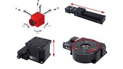
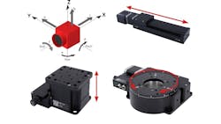
The first step in determining your vision system’s motion control requirements is identifying the type of motion required. There are six degrees of freedom. They are based on translation, which is the linear pushing, pulling, carrying, or lifting of a load along an axis (Fig. 1. a,b,c), and rotating or tilting a load around an axis of motion (Fig. 1. d,e,f). In general, motion control components are designed to provide rapid and accurate movement in a single degree of motion while minimizing unwanted movement in all others.
Anatomy of a Motion Control Device
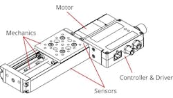
Moving an object on its intended axis requires five key components:
- Mechanics to securely mount a load to and guide it along its axis of movement.
- A motor to produce the mechanical force to move the load.
- A motor driver to supply the motor with the correct currents at precise timings.
- A controller to provide a data interface with the driver.
- Sensors to calibrate and measure positioning along the axis of travel.
While each of these components can be sourced and integrated independently, Zaber's (Vancouver, BC, Canada; www.zaber.com) X-Series devices combine all of these components into a single positioner (Fig. 2).
Key specifications
Matching the capabilities of the available motion control options to your vision system’s requirements will ensure your system can perform its intended task quickly and reliably without adding unnecessary cost or complexity. For example, a semiconductor packaging system will have different requirements for accuracy and repeatability at different points in the system. It will require nanometer-level accuracy and repeatability for picking and placing chiplet dies but may only require millimeter-level positioning for placing the completed ICs into carrier tape reel pockets. This section will cover the key specifications used to define the capabilities of motion control devices. The factors influencing these specifications will be the focus of Part 2 in this series.
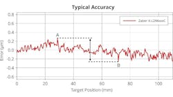
Accuracy is the maximum error possible when moving between any two positions on an axis of travel (Fig. 3) when both positions are approached from the same direction.
Repeatability is a measure of how accurately a stage can return to the same position over multiple movement cycles from the same direction. It is the maximum deviation in actual position.
For automated inspection and control of high throughput industrial processes, where minimizing cycle times is critical, repeatability is frequently more important than accuracy. High repeatability ensures that once a system has been calibrated, it will carry out a repeated sequence of motions with a high degree of consistency, eliminating the need for fine repositioning, which would increase cycle times and reduce throughput.
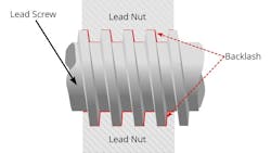
For vision systems that rely on the movement of the target or the camera to achieve fine focus control, backlash is a key performance specification. Backlash is a measure of the slack in a mechanical system (Fig. 4.), which can have a significant impact on the accuracy and repeatability of small movements. Backlash has its greatest impact on the accuracy and repeatability of stage positioning when the direction of travel is reversed, as the slack in the drive system must be taken up before the load will be moved. An inspection system attempting a fine focus change smaller than the backlash of the motion control device that drives it will not result in any change of camera or sample positioning. Note that some manufacturers do not use the term “backlash”; they report it as the difference between unidirectional and bidirectional repeatability.
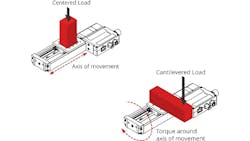
To ensure your system will perform as required, selecting a stage that can effectively support and move the required load is critical. The maximum centered load (Fig. 5) is the largest force that can be applied to the stage perpendicular to the axis of travel while maintaining reasonable performance and device lifetime. Load measurements are given in force units (Newtons) rather than mass (kilograms), as loading could come from a combination of a mass, gravitational loading, and other sources. The magnitude of these forces will depend on the mass of the object mounted on a stage and the way it is moved. A light object moved very quickly can result in greater forces than a much heavier object moved slowly.
The maximum centered load be calculated with the following formula:
F(in Newtons) = Mass (in kg) x Acceleration (in m/Sec2)
Under most conditions the acceleration of a centered load will only be due to gravity which can be approximated as 9.8 m/s2.
Cantilevered loads apply torque to a stage around the intended axis of movement (Fig. 6) and will result in uneven loading of its bearings and increased friction. You can calculate the magnitude of the cantilevered load with the following formula:
Cantilevered Load (in N⋅m) = Force (in N) x Distance (in m)
Speed and thrust are key selection criteria for any motion control device. High speed and thrust are particularly important for high-throughput applications where minimizing cycle times is essential. Maximum thrust is measured in Newtons and is the largest force that the stage can apply in the direction of travel. Maximum speed is the fastest the stage can move with no load.
Extremely high speed and high thrust devices are available. However, if image acquisition or processing times are the bottleneck of your vision system, paying more for faster motion control devices will not yield a decreased cycle time or increased throughput.
Motion control devices with high thrust and speed may unlock significant cost savings for cameras, particularly when high-resolution cameras are required. If a target can be rapidly decelerated and accelerated again, it may be possible to use rolling shutter cameras in place of cameras with much more expensive global shutter sensors without negatively impacting cycle times or system performance.
Tip
Review the cantilevered loads in your system at both ends of its travel. The cantilevered loading on the stage (a) will increase as the load is moved along its range of travel (b).
When combining multiple devices, consider how they are mounted to each other. A vertical stage mounted on top of a linear stage will apply a centered load to the linear stage (c). A linear stage mounted on top of a vertical stage will apply a cantilevered load to the vertical stage (d).
The combination of thrust and speed will impact the lifespan of the stage. Greater loads moving at higher speeds will exert greater forces on the stage. This will generate more heat in the drive mechanism, leading to faster wear of the mechanical components. For applications requiring long-term operation at high speed and thrust, paying more up-front for a device with significant overhead on the maximum speed and thrust specifications can yield significant long-term savings. Uprated motion control devices will deliver longer service lives and reduced maintenance requirements. The relationship between speed and thrust and the factors that influence them will be discussed in greater detail in Part Two.
While mechanical specifications are clearly important for motion control devices, electrical specifications should not be overlooked as they will impact the ease of system integration. Controllers with IO lines are ideal for use in high-throughput machine vision applications. Output lines enable highly reliable, low latency camera triggering with little setup effort. Cycle times can be minimized by immediately triggering cameras when a stage has reached its target position. IO triggering is an easy way to ensure that your production or inspection system’s motion control, lighting, and imaging components remain synchronized.
Care should be taken to match the nominal voltages of the IO between devices. +5V TTL is common for the digital outputs of many motion control devices but may exceed the recommended input voltage of some low power +3.3V single board computers that lack opto-isolated inputs. Most machine vision cameras from major manufacturers have opto-isolated input pins and will support +5V inputs.
Advantages of Integration
While it is possible for vision system designers to source and integrate discrete image sensors, FPGAs, image signal processing IP cores, and interface back-ends, most users prefer the convenience of preassembled cameras. The same is true for motion control. Sourcing, determining compatibility, configuring, and calibrating discrete stages, motors, drivers, and controllers can be a complex and time-consuming process. Motion control devices with integrated controllers and drivers simplify the device selection and setup processes.
Devices with integrated drivers and controllers that share a common control protocol further simplify system design. By working together seamlessly, out of the box as motion control building blocks, such devices can quickly be combined and recombined as your automation needs change.
Building systems requiring the coordination of movement across multiple axes with lighting, image acquisition, and processing is faster and easier with integrated controller devices sharing a common control protocol and API. Minimizing the number of libraries required for custom application development can result in smaller, more efficient applications, which are more easily maintained and are better suited for running on embedded systems with limited resources. Devices that share a common control protocol can also support daisychained configurations. Daisychaining enables multiple devices to be powered and controlled via a single cable from the host, simplifying cabling, and reducing costs. The single wire connection also saves space and frees ports or IO pins which are frequently limited on embedded systems.
Another advantage of integrated devices is that their unified design allows for streamlined, easy-to-use documentation. Troubleshooting an unexpected issue using a single comprehensive document is much easier than working out the potential conflicts between multiple independent components each with their own documentation.
Motion control is an essential element of automated production and inspection systems. Understanding the key specifications of motion control devices can help you optimize your designs to get the most from your vision system—and your vision system budget. Selecting the right motion control devices can help you quickly design, build, and deliver systems with faster cycle times, increased throughput, and greater reliability—all at a lower cost.
Part two of this article builds on the fundamentals covered here to explain the impact that different motor, drive, and bearing types can have on vision system performance. It will give you knowledge you need to further optimize your vision system designs.
