Vision-guided robots rack auto parts
New autoracking applications with 3-D vision systems improve automotive manufacturing performance and reduce costs.
By R. Winn Hardin, Contributing Editor
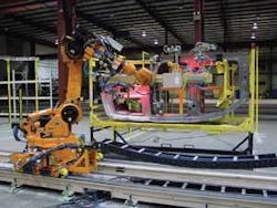
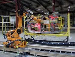
Unlike traditional two-dimensional (2-D) vision-guided-robot-system applications, new manufacturing applications require a robot to find a part on its own within a limited 3-D space and not depend on hard fixtures to hold the part, additional labor to load and orient the part, or upstream actuators, sorters, and feeders to singulate parts (see Fig. 1). Since 2001, DaimlerChrysler has taken the lead in deploying 3-D vision-guided robotics for autoracking applications, moving labor costs away from lift-assisted assemblies and other complex assemblies while using vision-guided automation to add flexibility to the manufacturing line. During the past four years, these systems have evolved from beta workcells to a broadly accepted manufacturing technology-an evolution that holds many lessons for vision and robotics suppliers, as well as integrators and end users looking to automate complex assembly tasks.
null
Designing robustness
DaimlerChrysler’s first autoracking application installed truck-bed parts in full-size Dodge pickup trucks at its Twinsburg, OH, USA, stamping and assembly plant (see Vision Systems Design, Oct. 2001, p. 45). The installation fell between a retrofit and a new installation in that the line was new, but the racks that held the stacks of 18 truck-bed parts were not new and were not designed for easy robot access.
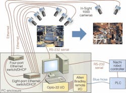
In this first application, six Cognex In-Sight 1000 cameras were mounted on the ceiling above a turntable to both inspect the rack and locate parts within the rack (see Fig. 2). After verifying the rack’s location and latch status (open/closed), the Cognex vision controller used edge detection and pattern-matching search algorithms on the acquired images to locate specific features in the images. The vision controller then passed the filtered images to Shafi RELIABOT supervisory software, operating on a PC host, which calculates the parts’ 3-D coordinates with six degrees of freedom based on the relationship and distortion of predetermined features in the images, such as locator holes, corners, and edges. RELIABOT passes the 3-D coordinates of the parts, which sit on a heavy-duty turntable that can hold two racks at a time, to the robot controller. The controller then directs the arm to correct the location and triggers the vacuum actuator to grab a part with suction cups.
According to Charlie Hemlock, project manager at Nachi Robotic Systems, this application was the first time the company used an additional camera mounted on the ceiling above the robot to measure the offset or how the part shifted between the suction “grab” and the final “clamp” of the part. The shift is usually caused by a thin film of oil on stamped parts. This offset correction enabled RELIABOT to make small, but important, changes to the robot’s path before it maneuvered the truck sidewall parts to the truck bed.
Designing the vision system for offset correction, Hemlock says, helped to guarantee the workcell’s success and led to a second installation at Twinsburg involving the assembly of “quarter-inner” wheel wells on minivans. This application used a similar setup with parts on a turntable. In this case, the parts were stacked vertically, so operators had to separate the parts and place them on chain hangers, which meant the part swung freely in 3-D space, challenging the vision system to guide the robot to a moving object. To enable the system to refine the robot guidance, the cameras were moved to the end of arm tooling.
In this arrangement-sometimes referred to as vision servoing-the vision system tracks moving parts without help from encoders or other nonvision sensors. Capturing the moving part with the robot’s suction cups took some trial and error. “On top of that, the parts were flimsy, so we couldn’t come at the part hard,” says Hemlock. “We had to float the robot into the part and grab it by turning on the suction at the right time. Also, there were two different models, and the robot’s suction cups had to be able to grab both types. By tweaking vacuum biases and using modular end of arm tooling made of adjustable aluminum extrusions and stanchions, we could change the clamp location easily and optimize the system quickly.”
Consistency is key
In 2003, DaimlerChrysler improved throughput by 90% by using 3-D vision-guided robotics to install floorboard/lids in Stow-and-Go minivans at its Windsor, ON, Canada, and St. Louis, MO, USA, facilities. According to James Mansour, advanced manufacturing engineering supervisor at the Chrysler Technology Center, his team learned several lessons between developing the Windsor workcell in early 2003 and the St. Louis South workcell in 2004.
Both workcells were essentially of the same design. In both cases, minivans with two storage compartments needed lids installed. The lids were stored vertically in a variety of racks of differing shapes and sizes. Mansour decided he could redesign and purchase all new racks, or use a vision system to find the part regardless of the type of rack used for shipping. After visiting other DaimlerChrysler autoracking workcells, Mansour’s team decided to improve the vision system’s part-location speed and accuracy by placing Cognex VisionPro cameras on vibration-free mounts near the workcell rather than mounting them on the ceiling.
The first installation was plagued by faults with the vision system, Mansour says, but not resulting from the vision hardware, software, or integrator. “It was our fault,” Mansour says. “The stamping supplier delivered inconsistent parts. We were producing parts from a trial die and not a production die, leading to inconsistency. When we went to a permanent die, everything worked.”
Mansour’s installation shared another challenge with a longitudinal rail installation workcell at DaimlerChrysler’s facility-namely ambient light. Both systems used IR LED arrays with matching filters on the cameras to illuminate the part and filter out ambient light from the plant; however, the workcell’s proximity to sunlight meant that on bright days the system would be overilluminated. “The philosophy was to light up the front of the part and use a black backdrop to increase contrast and ease edge detection, but in the winter the light was intense and would interfere with the vision system,” explains Joe Cape, advanced manufacturing engineering body-in-white supervisor.
During pilot builds and early production, tarps were used, but eventually a tinting film was applied to the windows, Cape says (see Fig. 3). Locating the cameras on the robot instead of in a fixed location put additional strain on the cables running from the sensors to the vision system and added to the potential need to recalibrate each camera’s coordinate system after a crash or an accidental nudge by an operator. Eventually the cables were changed to flex cable that would resist the extra movement. Cape also suggested that the integrator should install a second hard drive with all vision systems as back up. Last, Cape says he is pursuing a system that will help reduce the time required for recalibration.
Material Handling
While all of the systems primarily use vision to locate parts in a rack, the most recent autoracking installation at DaimlerChrysler’s Newark, NJ, USA, assembly plant significantly differed in the size and number of the parts in each rack and the overall complexity of the workcell. The application called for one robot to install several small parts and a second vision-guided robot to install inner and outer body sides.
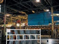
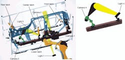
In addition to the standard challenges for a vision system, the Newark installation was a retrofit, so the racks could not be redesigned to be ‘robot friendly’ (see Fig. 4). This meant that the vision system had to verify that several latches holding the part had been opened by an operator. Because the latches could not be viewed from one location, the robot arm had to be programmed to rotate a camera around the rack, and verify that the latches were undone-all while using the same optics and setup required to locate fiducials on the part for later 3-D location. Some of the latches needed to be checked before every cycle because gravity could cause one latch to fall back in place.
Three end-effector-mounted cameras provide the images for 3-D and 2-D part location by Shafi’s ReliaBot software. According to Chris Byrne, CEC Controls vision-systems branch manager, CEC would normally use just a two-camera stereovision system for this purpose, but the size of the part (approximately 12 ft long) meant that a third camera, focused in the wheel well area, was required to provide a 2-D offset to compensate for part distortion. “Positively locating the A-Pillar isn’t good enough when the back end of the part can be skewed or twisted,” explains Byrne. “We had to choose whether to use camera #1 and add cycle time or add a third camera to maintain the specified pick tolerance.”
Because the inner body sides are shipped tightly stacked together, the robot used suction cups to temporarily pick up the part from the rack and then clamp it into a fixed position after clearing the rack. To correct for the slippage during this process, a fourth camera was installed in the ceiling to provide a 2-D offset before placing the part into the tooling.
The part’s rigidity also required special attention at the actuator. The large end-of-arm tool supplied by Comau Pico included five clamps. Next to three of the clamps, CEC specified a triangular grouping of three proximity switches to compensate for distortion in the part. By measuring the voltage from each of these switches, the robot controller could determine whether the part was close enough to grasp the part with the clamps or whether the robot needed to make small skew adjustments to clamp the part cleanly. “When we had all proximity switches made, we gave the system a ‘go’ signal,” Byrne says.
The most challenging aspect of the Newark installation was not directly related to the vision or robot systems but to one of the prexisting indexers or rack conveyors. Because the racks for one set of parts were widely spaced, these racks needed to be constantly loaded and rotated to the robot workcells on each side of the line to maintain throughput. The preexisting indexer is a U-shaped, side-by-side rack transfer system. One conveyor brings parts to the line from a loading station, a second cross-conveyor feeds racks to the robot station, and a third conveyor takes empty racks back to an unloading station away from the line.
After installing the station, DaimlerChrysler’s AME truck group supervisor Brett Antenucci and his team realized that rack movements were jostling the parts in racks that had been unlatched, but not yet assembled, resulting in overlapping parts and potential crash situations. The team solved the problem by adding variable-frequency drives to the conveyor system, which gently accelerated and decelerated the racks so as to not jostle the unlatched parts.
“We learned three lessons,” explains Antenucci. “First, we are going to make vision our recommended way to handle large parts like this. Second, system reliability was much better than we thought. We feel that the vision system-operator interface, everything-has made a quantum leap forward. Third, we’ve come to realize the system needs to be designed as a whole. If you want a robot and vision system to load and unload, it brings a new level of requirements to material-handling systems such as turntables and side-by-side rack transfer systems. In the final analysis, we have improved throughput and eliminated several operators. We’re quite happy with the systems.”
Company Info
CEC Controls
Warren MI, USA
www.ceccontrols.com
Cognex
Natick, MA, USA
www.cognex.com
Comau Pico
Southfield, Mi, USA
www.comaupico.com
Nachi Robotic Systems
Novi, MI, USA
www.nachirobotics.com
Shafi Inc.
Brighton, MI, USA
www.shafiinc.com
Utica Enterprises
Shelby Township, MI, USA
www.clean-dry-reapply.com
