Dual processors direct vision-guided robotic welders
Dual processors direct vision-guided robotic welders
Using dual processors and symmetrical multiprocessing software, an integrated vision system guides a robotic welder in a harsh factory environment.
By R. Winn Hardin, Contributing Editor
Giant, room-sized robots are of little consequence to the vision industry`s largest buyer--semiconductor manufacturers. To meet their stringent integrated-circuit (IC) production needs, these manufacturers are demanding small, compact, fast, accurate, reliable, and affordable vision systems for automatic wire
bonding or ball-grid-array (BGA) welding.
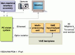
In response, companies such as General Micro Systems (GMS; Rancho Cucamonga, CA) are taking advantage of dual Pentium processors and the symmetrical multiprocessing capabilities of Windows NT to provide vision systems for robotic ultrasound welding machines. Capable of guiding a robotic welder at rates to 15 welds per second, the VME-based imaging system, dubbed VMEVision, has been developed by GMS as an automated microchip-packaging machine to operate in noisy factory environments (see Fig. 1).
Before welding can occur, parts must be identified. To do so, the system uses a dual-camera design. Using low magnification, the image processors find the relevant edges of the pins or ball grids on the IC being welded. Then, the VMEVision system switches between the cameras to a higher magnification. A correlation function between the image and stored libraries of the chip under weld or bond computes the welding point for a particular pin or ball grid. The next step is to find all the subsequent welding points and compute their x-y coordinates. This information is translated into motor-pulse units with a double-resolution, pixel-to-motor-pulse scale factor at the twin CPUs. This information is then transferred from the VMEVision system via the VME bus to the welder`s processor, which instructs the servo system and welder head to move at speeds of up to 15 welds per second.
Dual-head design
The dual-head camera that monitors the welding arm is positioned close to the 4-kV electrical spark energy generator used in the welding process. Because of this, the camera system uses tight cable shielding to eliminate pixel jitter. The VMEVision`s dual sensor-head camera resides on the welder head and a separate box houses an isolated power supply and twisted-pair wire that carries the I/O signals to the cameras. A signal-conditioning interface circuit, which resides in the VMEVision system, filters these I/O signals to eliminate external noise.
"The signal-conditioning interface of VMEVision is optically isolated from the camera," says Ben Sharfi, CEO of GMS, "They`re on two separate ground systems. With 4 kV of electrical power being used by the welder, a high-level of RF noise is generated and images have to be very stable."
Eliminating pixel jitter is crucial to VMEVision`s operation. "Otherwise, you`re calculating x-y coordinates on the wrong basis," says Sharfi. "This concern for system noise also affects camera choices," he says. "Because of this, we chose the XC-75 cameras from Sony Electronics (Park Ridge, NJ) because of their inherent low noise and low cost."
VGA or not
After isolating and filtering the camera signals, 1024 ¥ 768 camera data are digitized by one of two frame-grabber cards from Matrox (Dorval, Quebec, Canada). According to Sharfi, deciding between the Matrox Meteor half-size single-slot PCI card and the Pulsar full-size single-slot PCI card is a matter of what processing speed is required. "While, the Pulsar card uses an integrated VGA video output and on-board image processing, most welding applications only require the half-size Meteor card," he says. "Also, because the VMEVision`s motherboard features the 740AVGA controller chip from Intel (Santa Clara, CA), the VGA video capabilities on the Pulsar card are not always needed." The Meteor and Pulsar boards offer the same acquisition speed and 1024 ¥ 768-pixel resolution and can be expanded to acquire four camera inputs and plugged into the VME system via a PCI mezzanine carrier (PMC) board (see Fig. 2).
"Electrically, PCI and PMC cards are the same, but mechanically PMC cards are more suitable for factory automation because they provide lower capacitance and highly reliable connectors," Sharfi explains. Based on cues from the Intel Pentium II 500-MHz processors, the Matrox Pulsar PMC board switches the camera sensor heads from "free-running" mode during the stage`s continuous motion (larger steps) to "freeze" mode for position verification and fine tuning of the final movements of the robotic x-y stage and residing microchips.
High-clock speeds
Once digitized, images pass from the PMC through the 66-MHz PCI bus to the Intel 82443 BX North Bridge chip which operates as the memory controller, PCI controller and cache controller for the twin CPUs. From this point on to the twin CPUs and DRAM memory, the VME`s higher clock speeds of 100 MHz give VMEVision a considerable boost in performance. "That`s where the single board really shines," says Sharfi. "Unlike most boards you buy for the PC, this board allows you to capture and move the data into 1 Gbyte of DRAM," he adds.
Another benefit of the VME architecture is the image-transfer rate across the backplane. A Tundra Semiconductor (Kanata, Ont., Canada) Universe II CA9191420 chip acts as the controller interface for the VME backplane and PCI bus, allowing all the boards to communicate at a sustained 40-Mbyte/s rate to the servos, temperature controllers, welder, and x-y stage.
VMEVision also offers two Ethernet ports, allowing production engineers to receive the day`s task results through a factory-automated process line. The second port provides access to object libraries relevant to each chip configuration that guides the welder in its job or enables communications directly to another part of the plant for product tracking.
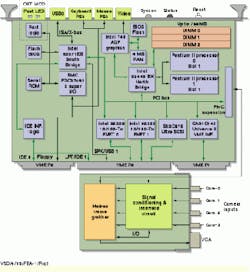
With the object libraries in DRAM memory, VMEVision passes the image data through to the twin Pentium II chips via the Intel north-bridge chip (see Fig. 3). This bridge chip handles communications between the processors and the memory cache by functioning as two PCI buses to keep information flowing into both Pentiums and into the Intel 749 Advanced Graphics Processor (AGP) for display. The AGP can handle up to four times the amount of image data of previous PC iterations, passing up to 532 Mbyte/s of image data between the monitor and VME board.
In addition to handling the display data, the bridge chip also funnels data into both Pentium processors. "That`s the beauty of NT," states Don Palmer, GMS software manager. "The application does not know which processor an application running on. At any given time, one image is being processed on the twin Pentiums while another is being brought in."
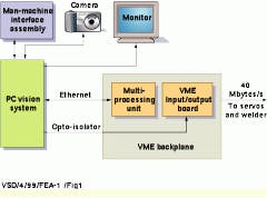
FIGURE 1. VMEVision system integrates dual high-speed Pentium processors, the symmetrical multiprocessing properties of Windows NT software, and real-time Ethernet reprogramming to direct the robotic welding of integrated circuits in a factory-floor environment. Two Ethernet ports deliver daily production summaries, access to integrated-circuit object libraries, and communications with other plant areas.
FIGURE 2. For image processing, the camera input data pass through a frame grabber and over the 66-MHz PCI bus to the North Bridge chip. From here, the imaging data move at VME clock speeds of 100 MHz to dual processors and DRAM memory. Based on actual chip image data versus stored chip library comparisons, the dual processors translate pixel information into motor-pulse units that control welder positioning and activation.
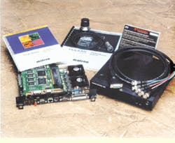
FIGURE 3. For robotic-vision applications, the VMEVision system provides custom programming capabilities and rugged VME-based boards with the graphical user interface of Windows NT (top). It also incorporates the low-capacitance, reliable connections of a PCI mezzanine board for industrial applications that must withstand harsh factory environments (bottom).
