Linescan cameras inspect steel
Custom design and off-the-shelf components measure the height of steel strips.
By Richard Meester
In hot strip milling, strips of metal are formed by passing steel between rollers revolving at the same peripheral speed and in opposite directions. To change the shape of the material, the roller-press settings are adjusted such that the material is as flat as possible. This increases the quality when the material is cooled, since water used in the cooling process flows evenly over the material. This results in a high-quality product with low internal stresses.
To control the pressing stations, the strip shape and surface must be measured to adjust specific parameters of the roller pressing stations. Such measurements require the height and surface of the strip to be accurately measured and provide feedback to the system to automatically control the roller presses. To do this in a hot strip mill at Corus, Quest Innovations and Technobis have developed a system based on multiple linescan cameras.
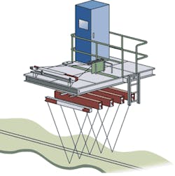
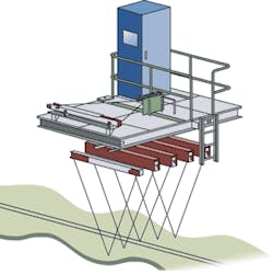
In the system design, there are six 1024 × 1, 8-bit, 27-kHz Spider 2 Camera Link linescan cameras from Dalsa. Five of these cameras are mounted in five cassettes above the steel as it emerges from the press (see Fig. 1). The sixth cassette is mounted on a calibration bench and can be used as a replacement should any of the other cassettes fail. These five 2-m-long measurement cassettes were custom-built by Technobis and each holds a 1135/P laser from JDS Uniphase, a mirror, optic technology, and the camera system. Each one of the cassettes provides a synchronization signal, power for the laser, and camera system. The five cameras are attached to a cart that is positioned above the strip.
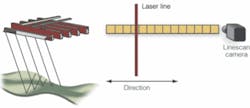
To find the height of the strip, a structured laser light illuminates the strip as it passes under all five cameras. Height information is then calculated by laser triangulation (see Fig. 2). Depending on the width of the steel, between three and five cameras can be used. The cart that holds the cassettes can be adjusted so that the width between the cassettes is adjustable to the width of the hot strip. Each cassette holds a laser and a camera to form the laser triangulation system. The laser spot is structured onto the steel at a predefined angle. Mirrors are used to modify the laser spot size, thickness, shape, and position (angle). The camera views this laser at a predefined angle through a mirror. Laser triangulation calculates the height of the steel.
Since each of the five cameras is synchronized, the profile of the metal sheet can be calculated. With this information, the total length of the sheet of metal that each cassette has measured can be calculated. Because the steel strip can reach speeds of 15 m/s, the cameras placed 2 m above the production line result in 0.4-mm resolution accuracy. Although the cameras need to be synchronized, height and width calculations can be performed separately within the cassettes.
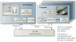
Since the cassettes are not close to the control system, each of the cameras in the cassettes is connected to a Quest Innovations Raptor-100 that interfaces the cameras to Gigabit Ethernet. The data are then fed into a switch from 3Com that is connected to the control system via Gigabit Ethernet and an Intel PCI-X Server Adapter for optimal performance (see Fig. 3).
To control the system, Quest chose a Compaq Proliant DL380-G4 from Hewlett-Packard (HP) that uses a DAQ-2213 digital I/O card from Adlink Technology to interface to analog and digital inputs and generate control signals. The control system runs the software that performs calculations that are not camera-specific and interfaces to the factory’s remote system to control the roller pressing stations.
Measured data can be automatically retrieved by the operator from this remote system. Data also can be retrieved using standard database software to monitor the steel-production process. Besides digitizing all the raw image data, all I/O and cassette information are logged into a database, which can later be analyzed offline.
The HP Proliant system is connected with two GigE connections to the 3Com network switch. This switch connects to all six cassettes, five of which are placed in the measurement system and one in a calibration bench. This spare cassette can be configured while the system is operational. To synchronize each of the cassettes with the Proliant, a sync signal is generated from the digital I/O card. Additional I/O is used to read the strip speed, control the lasers, and move the system to a position where it can be serviced.
In the service position, a simulation of a hot strip consisting of a well-defined sinusoidal “strip-shape” is placed on a motor. After the test has elapsed, all data are put in a calibration report file, which is checked by the operator. Any measured values that are not within a predefined range will instruct the operator to switch a specific cassette with the spare cassette and perform the test again.
In the future, it will be possible to upgrade the system using the company’s Raptor-1000, which features a camera, processing unit, and Gigabit Ethernet interface based on the same technology as used in the Raptor-100. This would replace the Dalsa linescan cameras and the Camera Link interface between the camera and the Raptor-100.
Richard Meester is president and CEO of Quest Innovations (Wieringerwerf, The Netherlands; www.quest-innovations.com).
Company Info
3Com
Marlborough, MA, USA
www.3com.com
Adlink Technology
Irvine, CA, USA
www.adlinktech.com
Corus
IJmuiden, The Netherlands
www.corusgroup.com
Dalsa
Waterloo, ON, Canada
www.dalsa.com
Hewlett-Packard
Palo Alto, CA, USA
www.hp.com
JDS Uniphase
San Jose, CA, USA
www.jdsu.com
Quest Innovations
Wieringerwerf, The Netherlands
www.quest-innovations.com
Technobis
Uitgeest, The Netherlands
www.technobis.nl


