Imaging the Tube
Winn Hardin, Contributing Editor
Solyndra manufactures tubular solar modules for rooftop installations. A copper indium gallium selenide (CIGS) thin-film material is applied to the inside of a glass tube so that the module can collect light from virtually any direction—direct, diffuse, or reflected. The key components are the glass tubes, each module comprising tubes measuring 15 and 22 mm in diameter and approximately 1 m in length.
When manufactured, the tubes are formed, cut, and fused through a heat treatment to round off the cut ends. For best operation, the ends must be even, smooth, and free from chips, scratches, and other defects. In addition, the bow of the 15-mm tubes must not exceed set parameters. To verify that the incoming tubes meet these specifications, Solyndra asked ATS Automation (Cambridge, ON, Canada) to develop a system that would inspect the tubes at speeds up to 3400 tubes/hr.
ATS Automation designs, builds, and installs custom manufacturing and vision solutions. For Solyndra, ATS Automation built two varieties of tube inspection machines (one for 15-mm and one for 22-mm tubes) that use as many as 20 Opteon Gigabit Ethernet cameras, at up to 2-Mpixel resolution with Power over Ethernet (PoE) capability that reduces cabling requirements and simplifies operation and maintenance. The cameras are installed in groups for various tasks and use two different colored light sources with associated narrowband filters so all inspection steps can be conducted simultaneously without light contamination. ATS Automation selected its ATS Cortex model 812 vision processors, running ATS SmartVision software, to provide the computational backbone, lighting, and communications center for the vision system. It communicates with an Allen-Bradley ControlLogix programmable logic controller (PLC), which tracks all production and handles loading, camera triggering, and unloading of the inspected tubes.
Handle with care
The cut glass tubes arrive in palletized plastic shipping containers. An operator removes the plastic wrap and loads individual trays of 144 tubes onto a conveyor that feeds the inspection system. The tubes lie horizontally inside the tray. While the dunnage is made specifically for the tubes, they can still move during shipping, which results in scratches and cracks near the tube ends. This is unacceptable for Solyndra’s solar module; the condition of the glass ends where electrical connectors will reside is critical to the module’s operation.
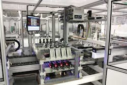
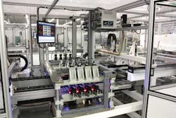
To begin the inspection routine, the PLC directs a gantry robot to pick up multiple tubes, repitch them, and place them on the inspection conveyor using a preprogrammed robot path. The inspection conveyor includes rows of plastic nests that hold each tube at the proper pitch—or distance center-to-center—for the upcoming inspection task. To achieve throughput speeds up to 3400 tubes/hr, the cell inspects four tubes at once (see Fig. 1).
Simplified cabling
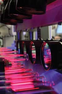
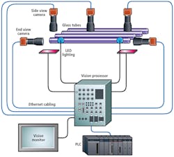
To inspect each tube, the PLC triggers a riser that lifts four tubes above the conveyor. The end of each tube must be inspected for the aforementioned defects, which means the system must inspect the entire 360° circumference of each tube. When the tube reaches the proper height, the PLC triggers a servo to turn the tube around its long axis, which will allow the cameras mounted above to collect images around the tubes’ entire circumference. A servo motion controller card in the PLC generates 24-V position triggers based on tube rotation. These signals in turn tell the three ATS Cortex processing units that control the machine-vision and lighting systems to begin collecting images from the 20 cameras and trigger the Ethernet-strobed, red and blue LED lighting from CCS America as necessary for inspection of the glass tubes.
“Each tube we inspect has five cameras,” explains Jay Stavnitzky, senior vision engineer for ATS Automation. “Two cameras look straight into the end of each tube. Two more cameras look at the sides of the tube near the end; and a fifth camera looks for bow along the length of the tube” (see Fig. 2).
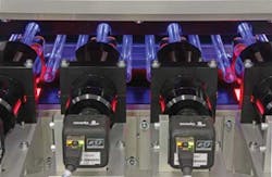
“We chose the Opteon cameras for many reasons, but most important, it was their Ethernet capabilities: Power over Ethernet, Ethernet triggering, and Ethernet light strobing all allowed us to run a single cable from the ATS Cortex system to each camera, and a second cable driving each [CCS] LED light,” adds Stavnitzky. “This really cuts down on the cabling costs” (see Fig 3.).
Stavnitzky placed one 2-Mpixel camera horizontally to look at each end of each tube (×4 for four tubes), and then another camera above the tube at each end to look at the sidewalls near the end of the solar tube. The fifth camera, which requires VGA resolution of 640 × 480 pixels, is mounted above each tube and looks down to determine if there is any bow.
Shining moment
The end view, side view, and bow inspection routines transpire simultaneously. An ATS Cortex 812 vision processor can handle up to 8 cameras and 12 lights along with several I/O ports for trigger and timing. For each inspection cell, Stavnitzky used two or three 812 modules, depending on whether the inspection system was inspecting the 15-mm tubes (which require a bow check) or the 22-mm tubes (which do not).
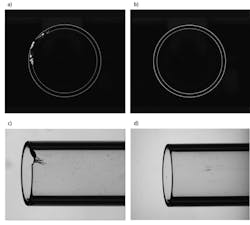
The system captures a number of images for each tube inspected. For the cameras mounted horizontally at each end of the tube, the ATS Cortex system acquires four images to check for inner fuse diameter as well as for gross defects using the ATS SmartVision circle inspection algorithm (see Fig. 4a and b). In the optical design of this system, the end view cameras, along with the side view cameras mounted above, required Melles Griottelecentric lenses to avoid perspective distortion; the single camera mounted above each tube for bow inspection requires a conventional optical lens.
As the tube is rotated, the side view cameras, acquire eight images at 45° intervals. “For the side view inspection, you only see a certain amount of light through the tube, and we’re looking for scratches. So, you have about a 45° window to ‘see’ the scratches as the tubes rotate,” explains Stavnitzky. In addition to locating scratches on the sides of the tube ends, the side view inspection also measure the outer diameter, end squareness, and average length (which is calculated from left and right side images), as well as gross defects (see Fig. 4c and d).
“For the bow inspection, we acquire 16 images and look for changes in the position of the side walls during rotation that would indicate unacceptable bow along the length of the tube,” says Stavnitzky.
After all inspections are complete, the ATS Cortex system sends pass/fail data for the tube along with its unique identification code to the Allen-Bradley PLC via Ethernet/IP protocol (see Fig. 5). The PLC then directs another gantry robot located above the outbound conveyor to separate defective tubes from acceptable tubes. The tubes are then manually taken to the next step in the tubular solar-cell manufacturing process.
“The system is all event-driven,” concludes Stavnitzky. “All the signals are 24 V and the ATS Cortex system only receives two trigger inputs because the same encoder triggers multiple cameras [over Ethernet], so you don’t need multiple trigger lines, simplifying the system. The ATS Cortex vision processor and Opteon cameras were the keys to this low-maintenance approach, allowing us to rapidly build the system with minimal cabling. The first system was designed, built, and shipped within 10 weeks.”
Company Info
ATS Automation Cambridge, ON, Canada www.atsautomation.com
CCS America Burlington, MA, USA www.ccsamerica.com
CVI Melles Griot Albuquerque, NM, USA www.cvimellesgriot.com
Midwest Optical Systems Palatine, IL, USA www.midopt.com
Opteon Cambridge, MA, USA www.opteontech.com
Solyndra Fremont, CA, USA www.solyndra.com
