Understanding laser-based 3D triangulation methods
Laser-based 3D triangulation systems can be configured in numerous ways to optimize the performance of a machine vision system
Wallace Latimer
Machine vision systems based on 3D triangulation are employed in a range of industries from automotive and electronics manufacturing to lumber mills. While the basic concept of measurement using triangulation is simple, there are a number of important details that must be addressed when implementing such systems. These include how laser-based 3D triangulation systems are configured and how laser line parameters are specified.
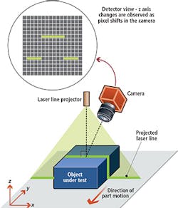
In laser-based triangulation systems, a narrow band of light projected onto a 3D surface produces a line of illumination that will appear distorted from an observation perspective other than that of the projector (Figure 1). Analysis of the shape of these line images can then be used to achieve an accurate geometric reconstruction of the object's surface shape.
There are four main components of a 3D triangulation system: the camera, the line projector that is typically laser-based, a mechanism that moves the object or camera/laser system through the field of view of the imaging system and software to process the captured image and accurately translate pixel offsets to height differences.
Triangulation configurations
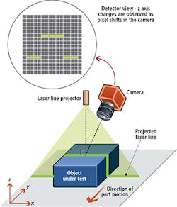
Laser line projection systems can be implemented in several different ways, each of which has its own unique characterics, advantages and disadvantages. Four of the most common geometries are shown in Figure 2.
In the standard geometry, which is the most commonly employed method, the laser line is projected perpendicular to the nominal measurement (x, y) plane. The most important characteristic of this configuration is that height variations in the object along the projected line do not produce a change in the line's y coordinate values. This simplifies the subsequent calculations required to derive object shape, resulting in a system that is faster, more accurate and easier to calibrate during setup.
One drawback of the standard geometry is that the camera views the object from an angle. This increases the depth of field it must accommodate to maintain focus as object height varies. It also means that the lens experiences greater magnification as object height (and hence object distance from the lens) changes. Thus a test object must be calibrated to derive accurate measurement results from the system.
It is also possible for there to be some occlusion with this geometry. Specifically, whenever the camera views the object from anything other than an angle perpendicular to the inspection surface, there will be some parts of the line which are blocked or occluded from the camera's view since no object is completely flat. This creates an inherent design tradeoff, because, while measurement height resolution increases for the standard geometry as the camera angle increases, so does the potential for occlusion.
Switching the positions of laser source and camera produces the reverse geometry. This setup offers increased height resolution over the standard configuration, since the oblique angle of laser illumination means a given change in object height produces a larger shift in the position of the laser line. Since the camera is normal to the measurement plane, there is no occlusion in this geometry.
However, in the reverse geometry configuration, a change in part height does cause a change in the line's y coordinate, making it more complex to interpret results. As a result, this setup is generally most useful with planar objects.
In specular geometry configurations, both the laser and camera are at similar, non-normal angles to the surface. Having both oblique projection and viewing angles provides greater height resolution over either of the previously described configurations. However, in this arrangement, it is possible for the camera to see specular, or near specular reflections, from the laser. This can cause measurement errors if these reflections produce saturation or blooming in the detector. On the other hand, higher reflection could be used to increase signal levels from dark colored objects since dark objects reflects less light, making the measurement signal level lower - in other words, the detector has less light to measure.
Working near the specular reflection angle generally provides the highest level of reflectivity for a relatively smooth object. Thus, when measuring a dark, smooth object, this geometry may be advantageous. However, if the object is highly textured, working at the specular angle may not yield much of an increase in reflectivity. Depending upon the color and texture of your object, it may or may not be necessary to work near the specular angle.
Once again, in the specular geometry configuration, a change in part height causes a change in the line's y coordinate, making it more complex to interpret results. Thus, this setup is best used when imaging planar objects. The oblique camera angle also leads to some occlusion.
In a look-away geometry configuration, both the camera and laser projector are placed on the same side of the normal to the object surface. This dramatically reduces the chance of specular reflections, unless the object is highly textured. However, this geometry also reduces height resolution because the camera point of view is so similar to that of the projector. There is also some occlusion in this configuration.
Of course, there are other possible ways to configure a 3D triangulation vision system that use a laser line source, but these are all typically variations of the four basic geometries just described and alternative methods will typically inherit the basic characteristics of the fundamental geometry from which they are derived (Table 1).
Laser line power
Knowing the parameters of the projected laser line is critical to creating and calibrating an accurate 3D triangulation system. All line projectors create a beam which is neither perfectly straight nor homogenous, and whose properties vary with distance from the projector. Only when these characteristics are understood and quantified can accurate measurements be obtained.
One key parameter is the power uniformity of the line beam, fluctuations in which occur due to manufacturing variations and tolerance effects. These typically manifest themselves as intensity variations (particularly at the beam edges), non-flat top intensity profiles, and light scatter (from poorly matched or fabricated systems). Each of these effects can lead to measurement errors.
Most laser line generator manufacturers specify line uniformity as the variation in the intensity profile from the average intensity value over a given region. Usually, this region is chosen to exclude the extremes of the beam edge, because this is where non-uniformities are typically most pronounced.
The problem with this approach is twofold. First, it does not prevent the beam from having large, absolute power variations, as long as they average out over the length of the entire beam. Secondly, it ignores the edges where beams are typically worst behaved.
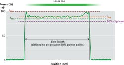
To avoid these limitations, Coherent has developed a stringent standard for beam uniformity which includes essentially the entire beam. Specifically, the beam edge is defined as the point at which beam power has dropped to 80% of its normalized, peak value. The average value for beam intensity must be maintained over this entire region and the absolute power level cannot drop below 75% of the peak value anywhere in this region (Figure 3). This creates a much more stringent uniformity requirement than just specifying an average value over a selected region of the beam.
This more rigorous definition delivers two important benefits to system developers. First, it yields higher power in the projected line for a given Center for Devices and Radiological Health (CDRH) safety classification, which translates directly into better signal-to-noise ratio (SNR) in the collected image, yielding a faster and more accurate vision system. This is because CDRH classification is based on peak power, no matter where it occurs on the beam. Thus, if there are power spikes at the beam edges (which is a common occurrence), while the middle section of the beam has a much lower power value, the safety classification will be based on the higher values.
Secondly, meeting this specification results in high unit-to-unit uniformity, which makes it easier for system builders to calibrate their product and maintain consistent performance. This occurs because having an absolute intensity floor in the specification limits the total amount of variation that can occur within the beam much more strictly than simply relying on an average value.
Laser line width
Even in the absence of manufacturing errors, the fact that the laser line is being focused produces variations in line width over its length, and width variations as the distance from the laser to the object under test changes. Furthermore, the magnitude of these variations depends strongly upon how the laser source is used to produce the line, so decisions about the line projector optics have a significant impact on system performance.
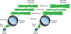
Most line projectors are based on diode lasers, which have a larger source size and lower divergence in one direction (the slow axis) than in the perpendicular direction (the fast axis). This is an inherent property of diode lasers due to the fact that their emitting facet is much longer in one dimension than the other. Laser line projection optics can be configured to expand either the fast or slow axis into the line length, and diffraction effects from this choice then influence line behavior in three important ways (Figure 4).
First, a smaller line width at the point of focus can be achieved by orienting the input laser beam so that the fast axis becomes the narrow dimension of the beam, and the slow axis becomes its length. This is important because a narrower line width delivers higher resolution and power density, which enables the ability to distinguish smaller scale variations in the height of the object under test.
However, diffraction also makes a more highly focused, narrow line spread more rapidly outside of focus than a wider line. Thus, achieving a narrow focused line width (and, therefore, higher resolution) necessarily comes at the cost of system depth of field (that is, the distance over which the line width expands to an unacceptably high level).
Finally, there is another, more subtle effect namely, that when a flat object is placed perpendicular to the path of an expanding laser beam, the edges of the beam must travel slightly farther to reach the object than the beam center. Since the beam is diverging over this added distance, the line width will be slightly larger at the edges than at the center (assuming that focus is set for the center of the line). This is commonly called the "bow-tie" effect. Again, it is more pronounced for a rapidly spreading beam.
Line straightness
A final laser line parameter worth mentioning is straightness. Real world projected laser lines are rarely perfectly straight. Most commonly, a bowed, or sometimes slightly "S" shape can occur. A bowed shape is most often caused when the incident laser beam enters the beam shaping optics at a non-normal angle of incidence.
Because line straightness is dependent on optical alignment, it may therefore vary from unit-to-unit, as well as over time in a given system. Proper system calibration is therefore required to take line straightness into account and produce accurate measurement results.
Although laser triangulation systems using laser line projection offer greater speed and accuracy than most other 3D vision technologies, system simplicity is deceptive. The results are critically dependent on several system parameters. Moreover, some vendors specify these parameters in an ambiguous and/or confusing manner. Thus, it is vitally important to understand how key system parameters are specified so that the final laser triangulation system is a good match in terms of cost and performance.
Wallace Latimer,
Product Line Manager, Machine Vision, Coherent, Inc. (Santa Clara, CA; USA; www.coherent.com)


