Mobile inspection system checks production line
Off-the-shelf components combine in high-speed system to check packaging machinery.
By David Lieberman, Contributing Editor
The manufacture of machinery for packaging lines may require visual inspection at speeds that can only be met by a machine-vision system. In the case of Multifeeder Technology, the company built a portable high-speed video-capture system to troubleshoot its packaging lines. Multifeeder’s core products are friction feeders, which are typically ordered as parts of turnkey packaging lines containing a variety of accessories such as conveyor belts, collators, wrappers, glue stations, and folding stations. When a customer orders a packaging line, Multifeeder builds that line at its own site, gets it up and running, and then disassembles it for shipment to the customer.
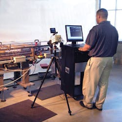
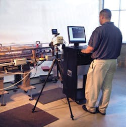
Recently, friction feeders and their associated equipment have gotten so fast that when problems arise, inspection personnel cannot see the source of the problem, explains Multifeeder spokesman Aaron Gysbers, noting that a current large packaging line has been particularly difficult to integrate. To image an area of interest, Multifeeder developed a process inspection system based on a high-speed video camera capable of continuous data streaming. To share the system across all the production lines being built at the company’s site, Multifeeder built it as a portable system on wheels. The total cost for the system was less than $20,000 (see Fig. 1).
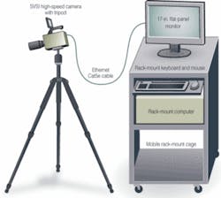
The Multifeeder portable troubleshooter consists of an industrial computer system in a rolling rack-mounted cabinet and a tripod-mounted GigaView camera from Southern Vision Systems (SVSI). Both the cabinet and camera have their own video display: a 17-in.-diagonal LCD monitor and a 3.5-in. LCD viewfinder, respectively (see Fig. 2).
FIGURE 2. Gigabit Ethernet provides a dedicated link between the video camera and industrial PC on the mobile inspection system.
“When an anomaly arises in a production line, we take some video and play it back immediately for the personnel configuring the system and make the proper adjustment,” Gysbers says. “If we spot a major problem, we can wheel the rack mount cage into our conference room and show it on the screen so our engineers can gather together and address the problem.”
CAMERA WITH A ROLE
The GigaView is designed for video recording and playback in process-inspection applications, capturing images of high-speed processes and turning them into slow-motion video for frame-by-frame analysis. It is based on a 15 × 12-mm CMOS sensor with 12 ×12-µm square pixels in a 1280 × 1024-pixel format, and it supports 10-bit monochrome and 24-bit color image capture. The camera provides a range of formats between 160 × 120 and 1280 × 1024 pixels and acquisition speeds between 60 and 417,000 frames/s. Shutter speed ranges between 2 µs and 20 ms.
The GigaView can capture between 25 and 112 s of video imagery in burst mode, while streaming mode delivers up to 8 h of imagery (2.4 Tbytes maximum) to the PC hard disk drive. The camera’s streaming-video capabilities were a major factor in the decision to use it, Gysbers says.
The camera, equipped with a Navitar C-mount zoom lens and 3.5-in. LCD viewfinder, mounts on a Bogen Manfrotto heavy-duty tripod with ballhead. It communicates with the PC over a dedicated Gigabit Ethernet link. In addition to internal and external triggering, the camera supports event-based triggering using SVSi’s proprietary image-cued triggering technology. “If you know what happens but not when, GigaView can look for the event and record digital video before and after the fact with a minimum of excess frames so that you can go straight to the cause of the problem,” says Bob Sharp, director of sales and marketing at SVSI.
The industrial PC is a 4U-high rack-mount computer from Industrial Computers with two 1.8-GHz, 64-bit AMD Opteron 265 microprocessors. They share 1 Gbyte of main memory and communicate with the camera over a 10/100/1000-Mbit/s Ethernet link using an nForce NIC (network interface controller) from Nvidia. They also share access to a pair of 36-Gbyte SATA (serial AT attachment) hard disk drives from Western Digital configured as a striped RAID 0 system.
The rack-mount cage in which the computer resides is a 20U-high Model 1920-3-000-20A20u from Rackmount Solutions. It also contains an ICI Model RK-2D 1U-high rack-mount keyboard/trackball, which stores in a lockable drawer. The monitor secured to the top of the cage is a Model VIE-Q171B Optiquest, a 17-in.-diagonal LCD monitor from ViewSonic with an 8-ms response time.
Unless programmed otherwise, the GigaView camera starts up in default-mode recording into a rolling buffer, capturing 10-bit monochrome pixels in a 1280 × 1024-pixel format with an 8-ms shutter time and 120-frame/s frame rate. The video can be stored in local memory, streamed to the PC, or discarded.
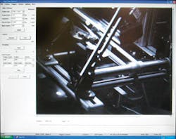
The camera has two modes of operation: record and playback. When the former is selected, a Record Wizard pops up and paces the operator through a series of windows to select format, frame rate, exposure, trigger source, and other variables (see Fig. 3). Image capture and data streaming are both effected with a single click on the appropriate on-screen button. Videos can be saved as raw GigaView (*mvw) files or AVI files. In playback mode, the screen displays the expected complement of video controls-forward, reverse, fast forward, and stop-and it lists the conditions under which the images were recorded.
PICTURING PROBLEMS
Two specific problem areas arose in a large Multifeeder packaging line. In this line, a friction feeder presents a standard envelope to a conveyor, which carries it to a folding mechanism that opens its flap. Next, a few beads of glue are applied to the envelope, another friction feeder places or “tips” a coupon onto the envelope, another mechanism pushes the flap back down onto the coupon and the envelope enters a shingling conveyor that terminates in a stacking station. The line also contains a reject mechanism, which comes into play when it’s determined by laser sensors that a coupon has not been placed on the envelope.
The problems related to tipping-the coupons were not being placed at the right location on the envelopes-and the reliability of the envelope transfer to the shingling conveyor. “The nice thing about a mobile system is that we can troubleshoot right on the production floor, make adjustments, and see results immediately,” Gysbers says. “And since the camera is on a tripod, it’s easy to set up a shot and troubleshoot, then move the camera down a few feet, set up another shot, and troubleshoot that area.”
null
