Flat-panel inspection demands precision
Using a combination of solid-state cameras, positioning equipment, and motion-control systems, developers are addressing FPD inspection.
By Andrew Wilson, Editor
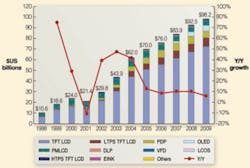
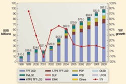
With the increasing use of flat-panel displays (FPDs) for TVs and computer screens, FPD manufacturing provides a major market opportunity for those involved in machine-vision inspection systems. Indeed, according to David Hsieh, vice president of DisplaySearch, total TFT LCD revenues for 2007 were $84 billion/year. By 2010, total worldwide revenue should approach $100 billion/year (see Fig. 1).
In the early 1990s, the first generation of FPDs sported factory display substrates of 300 × 350 mm. Today, FPDs of generation seven and eight are made on substrates of 1870 × 2200 and 2160 × 2460 mm, respectively, with screen sizes as large as 70 in. in diameter. Depending on the size of the screen, several different formats are currently available that range from XGA displays with 1024 × 768 pixels to WQXGA displays with 2560 × 1600 pixels.
With the increase in size of these flat panels, system developers are turning to sophisticated motion-control and inspection systems to perform material handling and defect analysis. “In some advanced systems the number of inspection stations is close to 30,” says Petko Dinev, president and CEO of Imperx. In these systems, digital mega-pixel cameras are used to control the FPD quality at every step.
A number of defects may be present at several stages of the production line, and so FPD inspection systems must achieve high accuracy, precision, and repeatability using high-performance area and linescan cameras, x-y-z positioning systems, and motion-control systems. To meet these demands, a number of motion-control vendors currently offer subsystems that integrators have used effectively in the design of their FPD inspection systems.
Detection/inspection
To understand the requirements, one only has to consider the specifications of current systems that have been developed for FPD production. The FPD Star system from NextTech Solutions, for example, can accommodate Generation 5, 6, 7, and 8 sized substrates and handle FPD panel glass that is 2.5 × 3.0 m. When equipped with optical inspection equipment, the system provides patterned defect inspection of features as small as 300 nm. To do this, the FPD Star uses a low flight-height air bearing support system, eliminating all contact on the substrate’s front and back surfaces. Glass holding and transport are achieved through the use of linear drives.
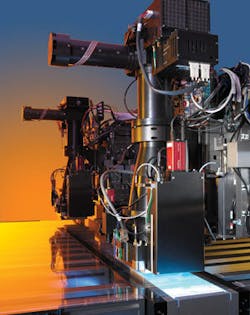
Inspection begins with raw glass inspection, where a set of several high-resolution cameras (typically 11 or 16 Mpixels) look for imperfections or defects with feature sizes less then 5 µm in or on the glass. To test the pixel voltages prior to assembling the color filter onto the array glass, for example, Photon Dynamics uses a CCD camera from Salvador Imaging in its Voltage Imaging Optical System (see Fig. 2). “This enables Photon Dynamics to optically image each pixel’s voltage and determine if it is defective,” says David Gardner, president of Salvador Imaging.
During the microlithography phase, cameras monitor the filter alignment with respect to the TFT pixels. Prior to assembling the FPD, glass spacers are placed on one of the FPD plates, in the non-active TFT pixel area. The spacers are placed every 10 to 20 pixels determine the accuracy of the spacing between the FPD glass plates.
“This process and, more particularly, spacer height are closely monitored using a set of four or eight high-speed VGA cameras,” says Dinev, “because any variation in the spacing between the FPD plates is directly responsible for image gray-scale nonuniformity and color purity. During the process of liquid crystal filling, high-resolution cameras monitor and identify the presence of gas bubbles. After the FPD has been assembled, cameras determine each defective pixel location. Depending on the size and the resolution of the panel, cameras with different resolutions are used.
“For small panels (up to 21 in.), 4-Mpixel cameras are used. For larger panels 11- or 16-Mpixel cameras are used,” says Dinev. In most cases these systems use between four and eight cameras. During the final inspection phase, the FPD is tested with a range of light levels, so the camera must operate with integration times from microseconds to several seconds. To ensure stable performance across this exposure range, some systems incorporate thermoelectrically cooled cameras.
Air bearings
To move each of the FPDs through the inspection process, most positioning systems currently use air-bearing carriages to transport the glass substrate used in FPD manufacturing with high accuracy, precision, and repeatability. While accuracy measures how closely the motion follows an ideal profile, precision measures how small motional increments can be, and repeatability provides a measure of how well the motion moves along the same path.
Air bearings offer the best of all these characteristics because they have excellent accuracy, precision, and repeatability. Because the components used in air-bearing designs are manufactured with tight tolerances and because of the air film’s averaging effects, the devices exhibit high accuracy. Typical linear accuracies are 10 µin./in. with maximum deviation of 100 µin./36 in. Air bearings also offer extremely good tilt characteristics-0.25 arc sec/in. And because air bearings exhibit no running friction, the achievable precision is only limited by the abilities of the motor controller/encoder. Positioning precision of ±1 encoder counts can be achieved using linear motors.
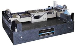
Currently, a number of vendors such as Aerotech manufacture air-bearing tables for the FPD market. Aerotech’s ABL9000 incorporates an active preload on both vertical and horizontal surfaces. The design utilizes large air-bearing surfaces that distribute load over a large surface area, resulting in a stage with outstanding stiffness making it ideal for the heavy and offset loads found in flat panel display processing. This motion platform provides greater than 1 m of x-y total travel and is constructed with a high-precision granite base and risers that act as a master reference surface. Aerotech’s proprietary air-bearing design maximizes angular stiffness, which minimizes turnaround times and step-induced vibration. Proprietary manufacturing techniques, dual motors and encoders on the gantry axis, and robust control electronics further enhance the dynamic performance (see Fig. 3).
Controllers and encoders
“Typical FPD inspection applications such as TFT color filter, bare glass, and patterned glass-array inspection require very fine resolution imaging with pixel sizes in the object plane on the order of 5-10 µm or even less,” says Barry Roth of DALSA. “This requires high-resolution cameras operating at fast linescan rates. In these applications consistent motion control and encoder operation are important to achieve the best image quality and measurement accuracy.”
Indeed, choosing the incorrect drive, motor controller, and encoder for such systems can result in reducing the overall accuracy, precision, and repeatability of the entire system. To overcome the limitations of the backlash, wear, and maintenance associated with lead, ball screw, belt, and rack-and-pinion driven motion-control and positioning systems, linear drives are often used (see Vision Systems Design, July 2005, p. 39). These offer a novel way of driving particular types of stages using a variation of the ac servomotor called the linear induction motor. Although more expensive than screw-driven systems, linear-driven systems possess the speed and lower inertia that make them more suitable in FPD inspection equipment that requires long travel lengths.
Replacing conventional ball screws and gears with servo linear motors increases performance of positioning systems, since both elasticity and hysteresis are suppressed, while bandwidth, overall precision, and resolution are increased. Since there is no lubrication required, mechanical transmission maintenance and operating costs are reduced when implementing direct-drive motors. Many manufacturers have used these drives in conjunction with air bearings to produce positioning systems for FPD inspection. Aerotech’s ABL9000, for example, uses a brushless linear servomotor with a noncontact air bearing and linear encoder to achieve a total travel of 1 × 1 m. With a resolution of 0.001 μm achievable with linear encoders and overall accuracy of ±5 μm, the repeatability of the drive is ±0.1 μm.
In FPD production systems, many different encoders can increase resolution. To obtain the highest resolution over the large distances required, laser interferometers are used for measuring position, providing accuracies up to ±1.5 ppm and resolutions to 0.3 nm. Although more expensive than standard linear encoders, the technology is offered by Aerotech to increase the resolution of its ABL9000 stage to 0.3-79 nm.
After selecting the type of stage, motor, and feedback, system designers can opt for a number of drive amplifier controllers and software to control their servo systems. These are often supplied by the companies offering complete x-y positioning systems or by third-party suppliers working in conjunction with them. PC-based, these systems consist of a master control digital I/O card for handling all the commands and data flow between the motion controller cards and separate motion-control cards to control the different x-y-z stages. In the design of its FPD inspection system, Advantech uses its PC-based PCI-1202 master control card to process motion instructions and data communications. The company’s ADAM-3212/J2S digital I/O slave modules are used to control the drives for camera or conveyor motions.
Other developers of FPD inspection systems, including Orbotech and Soonhan Engineering, have opted to use third-party motion-control products. Orbotech, for example, uses the SPiiPlus CM from ACS Motion Control to control the axes’ motion and I/Os in its systems. Each machine includes multiple axes.
While control of two or three axes demands the use of accurate linear motors, additional axes use smaller motors for simpler, less demanding motion tasks. Because of this, the SPiiPlus CM is configured to control the linear motors, while other axes are connected via a high-speed serial interface to external drives. APIs for C/C++ and Visual Basic or National Instruments LABView COM libraries are provided for system development.
To control the motion of its system, Soonhan Engineering used SynqNet from Motion Engineering. To reduce the number of wiring and connections, the digital SynqNet motion network has a single CAT5 cable running between motion controller, drive, and I/O modules. According to Soonhan, linear motor gantry systems designed with SynqNet are easier to build and troubleshoot than gantries designed with other network protocols.
Understanding FPD defects
In the manufacture of FPDs, the front and rear glass plates are produced in different production lines. In most cases, a number of displays are produced on one glass plate. In active-matrix displays, the rear glass plate is used as the substrate for the thin-film transistor. After color filter layers are applied to the top plates, they are aligned, combined, filled with liquid crystal, and sealed. Then, the large panels are scribed and broken, the edges ground, and the displays inspected.
During this manufacturing process, a number of defects can occur. These include bright or dark subpixel defects, inclusions, bubbles or blisters within the glass and liquid crystal, scratches on the glass and cracks, variation in the spacing between the glass plates or deformations on the panel’s edges and corners.
Of the millions of transistors on an FPD, a single failure may leave a subpixel permanently on or off, creating a dark or bright spot on the display. Since some degree of subpixel defects is inevitable, manufacturers must tolerate a minimal number of defects in their products. Minute specks of dust present during manufacturing can cause these defects. Of the 1.9 million pixels on a 1600 x 1200 UXGA display, for example, the failure of one subpixel represents a failure rate of 1 in 5.7 million (1600 × 1200 × 3) or 0.000017%, since each pixel is made from three red, green and blue subpixels. When possible, bright point defects are converted to less objectionable dark points through a repair process using multiwavelength lasers.
To regulate the acceptability of defects, the International Organization for Standardization has created a standard, known as ISO 13406-2, that identifies three classes for measuring pixel defects in FPDs. Class 1 panels are those that are defect free with no full pixel or subpixel defects. Class 2 panels are those with any or all of two full bright or dark pixels, five single or double bright or dark pixels, and two subpixel defects within five pixels of each other. Class 3 panels may have any or all of five full bright and/or 15 full dark pixels, 50 single or double pixels stuck on or off and five sub-pixel defects within a five pixel distance of each other. -A.W.
