Dual-camera system speeds part inspection
By Lawrence J. Curran,Contributing Editor
A manufacturer of machined-metal air diffusers that enable the instantaneous inflation of automobile airbags has graduated from manual inspection of the diffusers to a custom-developed vision-based system, and the results are impressive. The dual-camera apparatus accurately measures the height, width, radius, and certain angles of the diffuser derived from five exposures taken and processed in about one second.
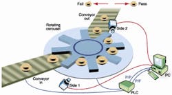
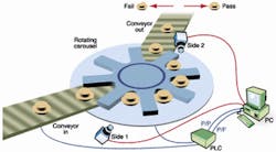
FIGURE 1. Machined-metal automotive airbag diffusers are fed from a conveyor (bottom left) onto a carousel or turret (center) that rotates them counterclockwise. The parts are positioned in the field of view of a camera (bottom) that captures side images, then rotated to a camera that is placed overhead (at right center) to measure the diameter. The programmable logic controller (PLC) at bottom right controls the overall inspection process, routing inspected parts that pass to be packaged for shipment; failed parts are routed to a reject location. The PC at far right performs image processing.
According to Greg Cala, director of project execution at Data Science Automation (DSA; Canonsburg, PA), developer/integrator of the air-diffuser inspection system, the customer, which supplies parts to the automotive industry, was able to eliminate as many as nine inspectors, as well as to accommodate a boost in production. The inspection error rate has decreased through use of the system, which also provides automatic data logging, allowing analysis of production trends, adds Cala.
"The challenge is to do things automatically that inspectors were doing manually with micrometers and calipers," Cala says. Data Science Automation specified the hardware, identified the vendors, purchased and integrated the inspection system, and mated it to the customer's materials-handling system." Then DSA wrote a software application that enables the programmable logic controller (PLC) used on this line to communicate with a PC, the cameras, lighting, and encoders that comprise the vision inspection system.
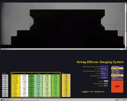
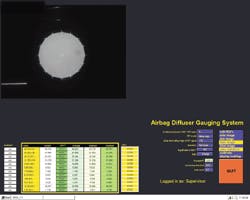
The airbag diffuser is a cylindrical part approximately 2 in. high, 1 in. in outside diameter, and 1/8 in. thick. The lower part of the tube is perforated with elliptical slots around the circumference, through which the gas is instantly dispensed to inflate the airbag. The last step in fabricating the diffuser is a stamping operation that opens these elliptical slots, Cala explains. Then the parts are conveyed onto a carousel or turret disk, which rotates them into the field of view of two model XC-ST70 CCD cameras provided by Sony Electronics Inc. (Park Ridge, NJ; see Fig. 1). One camera takes frontal or side views with the diffuser in a vertical position, and the second camera takes an overhead view, aiming down through the tube to measure the diameter (see Figs. 2 and 3).
PARTITIONING THE SYSTEM The system is designed to accept or reject a part according to how it compares with specifications stored in a file that contains acceptable tolerances. Motion control is governed by a PLC from Allen-Bradley Inc./Rockwell Automation (Milwaukee, WI), which communicates with the inspection application developed with LabVIEW software from National Instruments Inc. (NI; Austin, TX) using TTL signals. LabVIEW is a graphical programming development environment, which, in this application, runs on a Pentium II-based PC supplied by Dell Computer Corp. (Round Rock, TX).Data Science Automation uses NI-IMAQ and IMAQ vision tools for LabVIEW for image acquisition and analysis. Those tools include an NI PCI-1408 frame grabber, which connects to the cameras using a standard RS-170 link. "The application we developed in the LabVIEW development environment is driven by a queued-state machine architecture that works well for operation sequencing," Cala says. "And LabVIEW already includes library tools to perform tasks such as queuing data and reading TTL ports."
FIGURE 2. Silhouette of diffuser is generated using LED backlighting for measurements to be made at the points where red crosses appear. Those dimensions are then compared with the previously stored values of a known "golden part" while the diffuser moves to the overhead camera position.
The materials handling and overall production automation are controlled by the PLC. The parts to be measured are transported to the turret disk on a conveyer belt. This turret rotates every two seconds. The two cameras are mounted at two index locations in the turret. With each advancement of the turret disk, a TTL signal is received by LabVIEW from the PLC indicating a "part in place." LabVIEW then switches on/off the appropriate lighting device, triggers image acquisition, and performs the measurements.
Measurements are then put into a FIFO buffer or queue. The measurements derived from the first camera's image are integrated with measurements taken from the second camera's image. After all the measurements are processed by the PC, the LabVIEW application determines whether an accept or reject signal is generated and passed to the PLC over a digital hard-wired connection. Acceptance or rejection is determined by a comparison to the PC-based tolerance table, which is formatted as an ASCII file.
Cala points out that the LabVIEW application includes two utilities that allow a user to select and configure the measurement points. The "ROI browser" provides a user with the flexibility to add a measurement point and select a region of interest (ROI). It provides an input window to enter the edge-detection parameters for each point. Another utility calibrates the camera image to a specimen. "This utility allows a user to input the known measurements of the specimen," Cala says. An image is then acquired and measured in pixels. This action matches the pixels with the accurately known dimensions of a so-called "golden part," providing a calibration factor used to determine the dimensions of production parts.
ILLUMINATING THE PARTSData Science Automation designed three lighting subsystems into the airbag-diffuser inspection system. A 5632CW LED backlight from Illumination Technologies (East Syracuse, NY) casts a silhouette from behind the part so that the camera can take an image of its outer edges. The second source, an SLH 501L-30 helium-neon laser provided by Lasiris Lasers/ StockerYale Canada Inc. (Dollard-des-Ormeaux, Canada) creates a line on the part from the intersection of a sheet of light used to illuminate the rounded edges of the diffuser, enabling the analysis routines to determine the radius of the curvature of the edges, Cala says. The aerodynamics of the high-speed gas flow through the diffuser is very sensitive to these dimensions.Finally, an L53-953 fiberoptic illuminator from Edmund Industrial Optics (Barrington, NJ) assists in capturing images and measurements of the elliptical perforations stamped around the periphery of the bottom of the diffuser. Cala explains that this illuminator is mated to a solid, translucent plastic cylinder that is inserted through the sleeve-like diffuser to act as a light pipe. When the illuminator is inserted into the part, the glowing light pipe allows the camera to accurately view and capture—and the LabVIEW application to measure—the outlines of the perforations.
FIGURE 3. Images captured by the overhead camera provide the diameter of the diffuser being inspected, and those dimensions are compared and processed so that the PC can signal the PLC to route passed and failed parts accordingly.
Two side and two overhead images are taken, with the diffuser indexing 180° between exposures "because one view may not identify all the flaws," Cala says. Then the light pipe is inserted through the diffuser and one more side view is taken. The first side and overhead images are processed in the PC while the diffuser is moved into the field of view of the second camera, and those exposures are made. The final image is taken with the light pipe inserted to illuminate the perforations. The entire imaging process requires approximately one second per part, according to Cala, but the system speed is limited by the two seconds required for turret indexing.
The application developed using LabVIEW makes the pass/fail determination by calculating the measurements (using the previously determined calibration factors) of each inspected diffuser and comparing them to allowable measurements recorded in the tolerance file. The PC relays the comparison to the PLC, which directs passed parts to be packed for shipment, while failed parts are guided to a reject bin.
"The image-acquisition and image-analysis add-on toolsets, as well as the graphical user environment the operator sees on the monitor, are all integrated into the system using the LabVIEW development environment," Cala points out.
CHALLENGES AND ADJUSTMENTSHe describes the system integration for this customer as a two-phase project. After the system was installed and its performance was proven in about four months of production, "the customer wanted to do more with it because the engineers realized it could do more, such as inspecting for incorrect offset of the elliptical perforations at the end of the diffuser."Data Science Automation came up with the idea of the plastic light pipe inserted through the diffuser to better illuminate the perforations. The light pipe has to be wiped occasionally to keep it bright and must also be replaced when scratches hamper its brightness.
The chief challenge the company faced was in mastering the system timing, according to Cala. "Doing the whole job in a short, 1-s window was a challenge, especially when the customer came back to us and asked for four more measurements: one each of height and diameter and two of the heights of adjacent perforations, without taking more time." The company met the challenge by enhancing the application software to enable image analysis to be conducted in parallel with new image acquisition. "Rather than acquiring three images and then processing them, the processing begins as soon as the first image is acquired. LabVIEW allows us to do that—image processing in parallel with image acquisition."
The diffuser inspection system had to be integrated with an existing materials-handling line, working around hardware already in place to position the backlighting and cameras opposite each other to provide silhouettes of the diffusers.
"Between the time we designed the original system and the customer requested that the system perform four more measurements, a new version of the NI IMAQ analysis library was released, making it simpler and faster to do what the system had been doing before," Cala says. "As a result, we rewrote parts of the application to take advantage of these revisions. But instead of making all of the measurements in the same time, these enhancements actually allowed us to make them in less time.
"The continuing development and improvement of these tools allows us to provide high-performance applications that make our job easier; we can do a given task in less time for a customer," Cala concludes.
COMPANY INFORMATIONAllen-Bradley Inc.Rockwell AutomationMilwaukee, WI 53201Web: www.ab.comData Science Automation Inc.
Canonsburg, PA 15317
Web: dsautomation.com
Dell Computer Corp.
Round Rock, TX 78682
Web: www.dell.com
Edmund Industrial Optics Inc.
Barrington, NJ 08007
Web: www.edmundoptics.com
Illumination Technologies
East Syracuse, NY 03057
Web: www.illuminationtech.com
Lasiris Lasers
StockerYale Canada Inc.
Dollard-des-Ormeaux
Quebec, Canada H9B 3J1
Web: www.lasiris.com
National Instruments Inc.
Austin, TX 78759
Web: www.ni.com
Sony Electronics Inc.
Park Ridge, NJ 07656
Web: www.sony.com/videocameras


