Keys to Deploying Machine Vision in Precision In-Line Measurement Applications in Manufacturing
Machine vision tasks like quality inspection, identification, and robotic guidance might be the first to come to mind when considering this valuable technology in industrial automation. Just as important though is machine vision’s capability to perform precision, in-line metrology or measurement.
Automated, non-contact measurement, however, can present some unique implementation challenges in the execution of a robust and reliable application. This discussion will cover a few of these sometimes-overlooked key issues and some best practices that can help ensure application success.
Automated imaging is used in many off-line or laboratory metrology systems, too. However, this discussion focuses on systems integrated directly in the manufacturing process to deliver measurements of every part produced to help improve production efficiency and quality.
Non-Contact vs. Contact-Based Measurement
It might be obvious to mention that machine vision uses imaging technologies. Understanding the impact of this is critical when executing non-contact metrology using imaging. Differences between contact- and non-contact measurements are simple to describe but can be difficult to overcome, and in many cases, the results produced by these two techniques will not be aligned.
Related: Machine Vision and Imaging Trends in Automation: A View from the Trenches for 2024
A View From the Surface
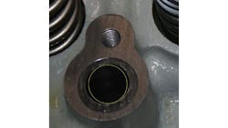
Regardless of the machine vision component used, an acquired image (grayscale, color, or even 3D) contains only a view of object features that generally face the imaging device. Where a manual measurement tool will have contact with, for example, the sides of an object at the measurement points, non-contact measurement must rely on visible edges of related features. Take, for example, measurement of the diameter of a machined hole or “bore hole” in a part.
A caliper or bore gage could be used to physically contact and measure the diameter of the bore at a point below the surface. However, an image from above the part measures only the edges of the hole at the surface of the part. Important questions are:
- Do these measurements represent the same exact thing physically?
- If not, is there a consistent relationship that reconciles any measurement differences?
This is a simple example of an underlying challenge that impacts almost any measurement application.
The Impact of Part Presentation
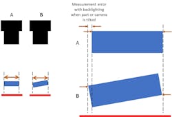
In a broader sense, part presentation and related production variations play a similar and perhaps more challenging role in contact/non-contact measurement disparities. Take, for example, the circular bore hole described earlier. When the face of that hole is perpendicular to the imaging system, the feature appears correctly as a circle in the image. However, if the part surface tilts even slightly, the circle will turn into an ellipse visually, impacting the measurement. This presentation problem can occur in nearly any in-line measurement regardless of the object or feature to be measured.
This issue is often more noticeable when performing measurements on a backlit part, and even the use of telecentric or “gauging” lenses does not overcome the potential error. With imaging for non-contact measurement, one must first mitigate all possible variation in part presentation, then understand that in almost any situation, any remaining part and/or presentation variation will introduce some stack-up error in the measurements.
Related: New Targets for OCT in Inspection and Metrology
An understanding of these underlying factors in non-contact measurement serves as a good starting point for success in machine vision in-line measurement, but there are several other points to consider in the practical implementation of image-based metrology.
Successful Imaging for Measurement Using Machine vision
From the discussions above, it might be apparent that the success of an in-line system rests with the implementation of correct and sometimes creative part imaging. What works best is often unique to a specific use case. However, certain best practices offer a foundation for getting the best imaging results. An important starting point for this discussion is a review of the concepts and language of the metrics of measurement.
Measurement Metrics—Precision, Accuracy, Trueness
Measurement results are commonly evaluated based on these fundamental and related measurement science concepts. It is important to clearly understand what the terms mean and how they impact the approach you take to designing machine vision measurement applications.
Precision is how close the values of a specific measurement are to each other over many executions. It is closely related to “repeatability” and “reproducibility.” In an in-line measurement application, precision is arguably the most important metric to consider as it indicates how trusted the reported measurement will be over time.
Related: The HEKUtip QC Assistant Delivers Precise Measurements
A common way to express precision is as the standard deviation (SD) of a set of measurement values with a lower SD indicating higher precision. However, averaging the data may not tell the whole story for in-line measurement. For many applications, the most useful metric is a basic range of measurement values over time. Because most in-line systems not only collect data but also must provide decisions regarding in- and out-of-tolerance parts, the extremes of a range can be used to reasonably predict the system’s capability to reliably pass and fail parts with minimum false rejects and few or no escapes.
But what about accuracy and trueness? Trueness is how close the mean of the measurement is to a real value. A measurement that is accurate has both high precision and high trueness. These values may be less practical for in-line systems because the “real value” that determines these metrics can be somewhat ambiguous or even variable in the production environment. However, a non-contact measurement system that has very high precision usually can implement a fixed bias in the measurement to bring the results in line with a stated true value.
Imaging Specification for Metrology
The basic image formation specification related to system precision in machine vision metrology is the spatial resolution of the acquired image. Spatial resolution is the estimated or measured size of an individual pixel (the smallest unit of imaging in a camera) in real-world units. Simply put, with a sensor that contains 1000 pixels in the horizontal direction, and optics that produce a field of view that is 1 inch in width, a single pixel would represent 0.001 inch in the resulting image. By dictating the selected sensor pixel count and/or the size of the imaging field of view, the spatial resolution can be specified to meet the needs of the application. But what are the needs of the application?
As a gauge, the smallest unit of measurement (some exceptions noted later) in a machine vision system is a single pixel. As with any measurement system, to make a repeatable and reliable measurement, one must use a gauge where (as a rule of thumb) the smallest measurement unit is one tenth of the required measurement tolerance band. This can be referred to as the gauge resolution. In the example I just described, the system with a 0.001 inch/pixel spatial/gauge resolution could be estimated to be precise for a measurement of approximately +/- 0.005 inch (a tolerance band of 0.01 inch, or ten times the gauge unit).
Sometimes these calculations might result in a surprisingly high number of pixels being necessary to make non-contact measurement reliable and repeatable with reproducible results for a given application. It is unwise and usually unsuccessful to make compromises in spatial resolution. The only guaranteed configuration is achieved with creative specification of imaging devices along with the use of measurement tools and algorithms appropriate for the application.
The Lure of High-Resolution Imaging
Advances in sensor and camera technologies have resulted in the availability of increasingly higher-resolution imaging for machine vision applications. This allows users to achieve necessary spatial resolutions with larger fields of view. While this approach is compelling in some use cases, the benefit comes with some disadvantages. One that is often overlooked is the challenge of lighting and imaging angles with larger fields of view. Providing uniform illumination or illumination with critical geometry can be difficult over large viewing areas. Optics with wide imaging angles, if used to obtain a larger field of view, also impact image quality with respect to feature extraction for metrology. One option is to use multiple cameras if appropriate.
High-resolution imaging though is a very acceptable option if these and other possible obstacles are overcome in the imaging design. Some applications also might benefit from the use of algorithms that expand the gaging resolution of the system.
Expanding Resolution Algorithmically
Sometimes improved gaging resolution is possible beyond the spatial resolution of an imaging system by using algorithms that report features to “sub-pixel” repeatability. Some examples would be gradient edge analysis, regressions such as circle or line fitting, and connectivity in some cases. The result is that the smallest unit of measurement, or gauge resolution, can be less than a single pixel, which could impact the necessary pixel count or field of view (FOV) size. In specification, the expected sub-pixel capability should be very conservatively included (if at all) with the understanding that while the sub-pixel capability can be estimated in advance, it can only be confirmed by testing the system with actual parts and images to empirically determine capability.
Related: How to Avoid Lighting Pitfalls in Machine Vision Applications
The Impact of Optics and Illumination
Successful imaging relies on creative use of optics and lighting. A complete discussion of best practices with these components in machine vision is beyond the scope of this discussion, but the impact of these components is still important. As a broad statement, the image must produce the best possible contrast for the extraction of the features to be measured with the lowest possible distortion. Specialty optics like telecentric lenses may be one option. Illumination components must highlight features with consistency in the face of part and presentation variation. In all cases, successful machine vision image formation requires experimentation, both in the lab and on the floor, to ensure the correct component selection.
Achieving and Measuring Performance
Use All the Right Analysis Tools
No discussion of image analysis can even begin without a reminder of one of the most basic machine vision paradigms: no software tools or applications can “fix” or overcome a bad image. Where necessary, tune or optimize the image sparingly but ensure the quality of the image first and then use analysis tools for exactly their purpose: the extraction and analysis of features in an image.
Most machine vision software libraries and applications have tools or algorithms targeted for measurement or metrology. These often have the capability to use multiple points to produce a result thereby “smoothing” the effect of small physical variations in the features. Some algorithms are not well indicated for measuring though. Generalized “search” tools can find features but must be used carefully as the tool might “fit” the result to a pretrained model without regard for localized variations that could impact the feature position. Note that these tools do not provide measurement information, but only search confidence, and they rarely are effective alone. Binary tools might not be practical in some cases either as consistency of the thresholding can change the geometry of the reported object or “blob.” Meanwhile, 3D imaging systems for metrology implement their own somewhat specialized but effective tools. And, while deep learning models can be trained to segment targeted features, measurement of those features is best performed with direct analysis tools.
Related: Software Basics in 3D Imaging Components and Applications
Calibration of the camera(s) in a metrology application is not absolutely required but benefits of calibration include:
- the ability to present real-world measurement results
- correction of image perspective for more precise measurements
- the ability to correlate images from multiple cameras
Calibration performed with a specific calibration article usually is an available function of any machine vision system or software.
Machine vision components and systems that acquire 3D data also are effective in some measurement applications. Systems using 3D range from very simple to very complex to integrate, but in some cases, 3D might be the only option. In the application of 3D measurement, it’s important to note that all the aforementioned measurement metrics and considerations still apply. It might be valuable to seek out expert assistance with 3D imaging, depending on your level of experience.
Error: Static and Dynamic
When testing a system to evaluate performance metrics, static and dynamic data collection help clarify the source of error in a machine vision measurement system. Static testing is performed by acquiring multiple images of the same part while it is in a static fixed position. The static test reveals the fundamental measurement capability of the machine vision components and software. With this knowledge as the starting point, additional testing of the measurements with dynamic part presentation over a large sample set reveals the contribution to error produced by the automation in the overall measurement system analysis. Usually, this error is larger than the error obtained in static testing.
Ultimately the dynamic testing results reflect the expected performance of the system. Some error stack-up from the automation and part handling process might be mitigated if better static results can be obtained by adjusting the imaging or optimizing the analysis performance. In many cases, though, the dynamic error may have to be improved in the mechanical part of the system including improvements to part handling and presentation.
Making it Work
There are, of course, many other important technical issues and considerations when it comes to implementing successful machine vision based in-line measurement systems. Hopefully this discussion has provided some insight into the specification and implementation process and encourages you to use machine vision in this important industrial automation application.
About the Author

David Dechow
With more than 35 years of experience, David Dechow is the founder and owner of Machine Vision Source (Salisbury, NC, USA), a machine vision integration firm. Currently, he also is a solutions architect for Motion Automation Intelligence (Birmingham, AL).
He has been the founder and owner of two successful machine vision integration companies. He is the 2007 recipient of the AIA Automated Imaging Achievement Award honoring industry leaders for outstanding career contributions in industrial and/or scientific imaging.
Dechow is a regular speaker at conferences and seminars worldwide, and has had numerous articles on machine vision technology and integration published in trade journals and magazines. He has been a key educator in the industry and has participated in the training of hundreds of machine vision engineers as an instructor with the AIA Certified Vision Professional program.


