Fundamentals of Line Scan Imaging, Part 1: What It Is and When to Use It
Editor's note: This is the first part of a two part series on line scan imaging in machine vision. Read Part 2 HERE.
What you'll learn in Part 1:
- What line scan imaging is and how it differs from area scan imaging.
- The types of machine vision applications, such as automated web inspections, that are suited to line scan imaging.
What you'll learn in in Part 2:
- How to apply line scan imaging to automated inspection.
- How to overcome common technical challenges in line scan imaging.
Almost everyone is familiar with 2D, or area scan, images from everyday objects such as television, photography, and even artwork. In electronic imaging, including machine vision, the 2D image consists of a specific number of rows and a specific number of columns of pixels called the image resolution.
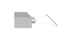
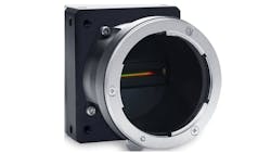
Line scan imaging, sometimes called 1D imaging, has only one row of pixels as illustrated in Figure 1 and Figure 2.
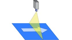
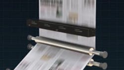
In most cases of line scan imaging, a 2D image is desired. To generate a 2D image, the part is moved under the camera, as shown in Figure 3, or the camera is moved over the part. As the movement progresses, successive scan lines are acquired. The number of scan lines acquired determines the number of rows in the image. For many line-scan imaging applications, there is no end to the number of scan lines acquired. In essence, the image has an infinite number of rows. A continuous image like this must be processed in real time; it cannot be stored.
Contact Image Sensors
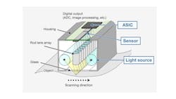
While the most common way to achieve line scan imaging in machine vision is using a line scan camera, there is a growing interest in applying a contact image sensor (CIS). A CIS is much different than a line scan camera (see Figure 4).
The CIS is really a misnomer since the image sensor is almost never in physical contact with the object; usually it is about 10 to 20 millimeters away from the imaged surface. A graded-index (GRIN) lens focuses light from the object onto the sensor. A CIS also includes built-in lighting.
Related: Next-Gen Contact Image Sensors Enhance Inspection of Batteries and Printed Material
Contact image sensors are an outgrowth of imaging for fax machines and document or page scanners. They work well for flat, moving surfaces and are very compact. The use of GRIN lenses gives contact image sensors telecentric-like properties eliminating distortion. While they are used mostly for flat objects, they can work well if there is some limited height variation.
Also, since contact image sensors have built-in lighting, the lighting may or may not be right for a given application.
The image sensor in the CIS is as long as the line of view on the object. For short lines of view, less than about 80 mm, only one image sensing chip is needed. For longer lines of view, multiple sensing chips are needed. When multiple sensing chips are used, they are either butted end-to-end or they are staggered. When butted end-to-end, there are a few missing pixels where two sensing chips meet. When staggered, image processing is needed to correct for the offset between neighboring sensing chips.
Area Camera Operating as Line Scan Camera
Modern CMOS area cameras have a programmable region-of-interest (ROI) that can be as small as a single row of pixels. With appropriate programming, an area camera can function as a line scan camera.
Typically, a line scan camera will have better performance than an area camera operating as a line scan camera. Bandwidth is usually higher for the line scan camera. Also, because the sensing elements (pixels) in a line scan camera are usually larger than an area camera and the line scan sensor has a fill factor very close to one, the line scan camera will have better signal-to-noise performance than the area camera.
For shorter line-lengths, less than 2,000 pixels, area cameras operating as line scan cameras may have significant cost advantages over line scan cameras.
Color in Line Scan Imaging
It is common to think of a line scan image sensor as sensing only gray-scale data, but there are common ways to build color-imaging line scan cameras.
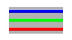
One technique for creating a color line scan image is to use three separate line scan sensors on the same silicon chip as shown in Figure 6. One sensor line has a red filter over it, another a green filter, and the third sensor line has a blue filter. This is a tri-linear sensor. Tri-linear sensors have three scan lines, red-green-blue. There are also quad-linear sensors having four scan lines, red-green-blue and infrared. Tri-linear sensors require tightly coupled timing between the motion of the part and the scan rate of the image sensors to permit color registration in the processing software.
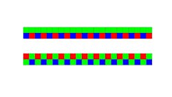
There are line scan sensors consisting of two parallel adjacent scan lines with red, green, and blue filters in a modified Bayer pattern (see Figure 7). Because the lines are immediately adjacent, the timing constraints are less stringent than for the tri-linear sensor. However, color interpolation is needed, and there is a loss of effective resolution due to the alternating color filters.
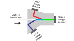
The highest quality line scan color imaging uses the three-chip camera diagrammed in Figure 8. This camera uses three line-scan image sensors mounted to a color separation prism. The three sensors are imaging the same line of view but with different portions of the color spectrum. This line scan camera requires special lenses designed to compensate for the optical effect of the color separation prism. One advantage of the three-chip camera is it provides high-resolution imaging with no special timing constraints.
SWIR
There are also short-wave infrared (SWIR) line scan cameras available. The SWIR spectrum, ranging from 900 nm down to 1,700 nm wavelength, is very useful for applications such as detecting water in objects. For example, SWIR will show bruises in fruit not evident in visible light.
Related: SWIR Imaging Enables Many Types of Machine Vision Applications
Hyperspectral Imaging
While not usually considered as line-scan imaging, the most widely used hyperspectral imaging approach, called push-broom imaging, actually scans a line across the field-of-view. A common way to make a hyperspectral camera is to image onto a slit, and this forms the scan line. Light passing through the slit spreads into a fan of wavelengths using either a diffraction grating or a prism. The fan is imaged with an area scan image sensor where the X direction corresponds to position along the imaged line and the Y direction corresponds to different wavelengths (see Figure 9).
Related: Using MWIR Hyperspectral Imaging to Battle Black Plastic Pollution
The result of image acquisition over an area with a push-broom hyperspectral imager is called a data cube (illustrated in Figure 10) where the X and Y dimensions of the cube represent the X and Y dimensions of the field of view, and the Z dimension of the cube represents slices of the spectral wavelengths.
Combined Bright and Dark Field Imaging
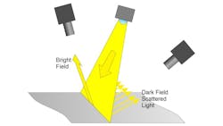
Bright-field imaging has the light source positioned so directly reflected light is directed into the camera’s lens. Dark-field imaging has the light source positioned so only scattered light is directed into the camera’s lens.
An application requiring both types of illumination is very difficult to achieve with an area scan camera. With line-scan cameras, two cameras can be positioned so one camera images directly reflected light and the other camera images scattered light as shown in Figure 11.
Applications for Line Scan Imaging
One-Dimensional Measurement
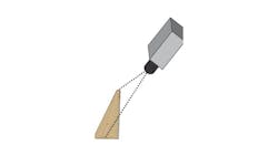
In some applications, such as guiding the edge of a web, a repeated 1-D measurement is all that is needed. A line-scan camera is ideally suited for these applications. (see Figure 12.)
Web Scanning
Many products are made in a web. A web is a continuous, mostly flat, material flowing along the production process. Some examples of products produced as webs are:
• Rolled metal
• Plastic film
• Non-woven fabric
• Woven or knit cloth
• Extrusions of various shapes
• Tape
• Optical Fiber
• Paper
• Printed material from a web press
• Movie film digitization
• Roadway and rail track inspection
Related: Line Scan Cameras Check the Quality of Laser Cut Parts
Some of these, such as extrusions and roadway inspection, are not flat. The common characteristic is that web inspection is virtually endless. The image acquisition and image processing approach must operate in real time.
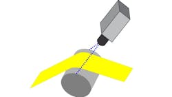
One challenge in imaging a flat web is to reduce the flutter or height variation. A common technique is to inspect the web while it crosses over a roller as shown in Figure 13. Another technique is to inspect the web held under tension between two closely spaced rollers.
Mass Conveying
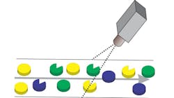
Some products are mass conveyed. The products are discrete, but they are conveyed in bulk with no organized arrangement, often on a conveyor belt as shown in Figure 14.
Examples are:
• Food sorting for grains, nuts, small fruits, etc.
• Sorting of recyclables, often after shredding
• Separating or grading ore for size or quality
This application is similar to web scanning with some exceptions. It becomes necessary to segment the items in real-time, and often it is necessary to operate a rejector or diverter, also in real-time.
Inspection of Cylindrical Objects
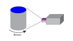
For critical inspection of the surface of a cylindrical object such as a bearing roller, a bearing race, or the label on a bottle, the part can be stopped and rotated in front of a line-scan camera to generate an image of the entire surface as shown in Figure 15.
Where the demand is for higher productivity and cylindrical parts cannot stop, applications tend to use arrays of area cameras with image stitching and rectification during image processing. Still, the use of line-scan imaging offers the potential to provide a higher quality image with less image processing burden.
Ultra-High-Resolution Imaging
There are times where flat parts need to be imaged at very high resolution; higher than is practical with a single area camera. In those cases, a line-scan camera can be moved over the part’s surface in a serpentine pattern like what is shown in Figure 16 to produce an extremely high-resolution image.
Alternatives using area cameras would be an array of very high-resolution area cameras, each being quite expensive, or moving an area camera over the surface which would require starting and stopping the motion.
Conclusion
In line scan imaging, a camera or sensor uses one row of pixels and builds up a 2D image by acquring successive scan lines. There are numerous machine vision applications for which line scan imaging is useful, such as scanning materials that are manufactured in a continuous web, such as paper or rolled metal.
In part 2 of our series on line scan imaging, we discuss how to apply line scan imaging and address common technical challenges. ACCESS PART 2 HERE.
About the Author

Perry West
Founder and President
Perry C. West is founder and president of Automated Vision Systems, Inc., a leading consulting firm in the field of machine vision. His machine vision experience spans more than 30 years and includes system design and development, software development of both general purpose and application specific software packages, optical engineering for both lighting and imaging, camera and interface design, education and training, manufacturing management, engineering management, and marketing studies. He earned his BSEE at the University of California at Berkeley, and is a past President of the Machine Vision Association of SME Among his awards are the MVA/SME Chairman’s Award for 1990, and the 2003 Automated Imaging Association’s annual Achievement Award.
