Fundamentals of Line Scan Imaging, Part 2: How to Apply It to Machine Vision Applications
Editor's note: This is the second part of a two part series on line scan imaging in machine vision. Read Part 1 HERE.
What you'll learn in Part 1:
- What line scan imaging is and how it differs from area scan imaging.
- The types of machine vision applications, such as automated web inspections, that are suited to line scan imaging.
What you'll learn in in Part 2:
- How to apply line scan imaging to automated inspection.
- How to overcome common technical challenges in line scan imaging.
Line scan imaging is very useful for specific applications, such as scanning products made in a continous roll, or web, but applying it to automated inspection of such products requires different technical considerations than with area scan imaging.
In this article, you'll learn how to apply line scan imaging to your machine vision applications and how to address common technical challenges.
Synchronization
A key requirement in almost all line scan imaging applications is to have the scan lines imaged at precisely regular intervals on the surface. Even minor speed variations can cause distortion of imaged features.
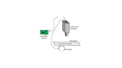
The common approach is to use an encoder to provide pulses for each increment of motion. Ideally, the encoder would deliver a pulse to trigger the camera to take a scan. (See Figure 17, the primary image above.) Sometimes the encoder does not provide pulses at the precise time needed. Some advanced motion controllers provide scaling to issue a trigger pulse at a specified interval of travel. Some line scan cameras and some frame grabbers designed to work with line scan cameras provide the ability to scale the pulses to provide a close approximation of the needed trigger interval.
Related: Automated Inspection System Detects Defects in Carbon Fibers
Exposure Timing
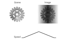
If the part speed varies and the camera’s exposure time is determined by the interval between trigger pulses, then the exposure time will vary leaving some areas underexposed and others overexposed as shown in Figure 18. Most line scan cameras allow the programming of the exposure time. The programmed exposure time must be shorter than the minimum period between trigger pulses. If a trigger pulse is received before the exposure for the previous scan is finished, there will be an imaging artifact. Some line scan cameras will ignore the early trigger; other line scan cameras internally delay the trigger until the current scan finishes. Either approach has the potential for missing scans.
Blur
Any time a camera images a moving object, there will be some degree of blur in the image due to the need for exposure time. The amount of blur depends on the exposure time of the camera and the speed of the object moving by the camera. By their inherent nature, line scan cameras have a blur no greater than the width of one scan line. The use of programmed exposure that is significantly shorter than the trigger interval can reduce the blur further. For most line-scan applications, blur is not an issue.
Related: Fast Semiconductor Inspection with High-Resolution Color Line Scan Cameras
Alignment and Calibration
By itself, a line scan camera produces only one line of image data. Acquiring a 2D image of a stationary target provides an image with only vertical artifacts (every row is identical).
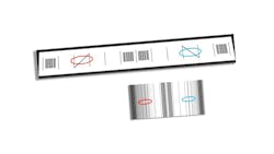
A simple target (as shown in Figure 19) provides the ability to enable focus and alignment. When using a line scan camera imaging a stationary part, an acquired image appears as vertical streaks in the 2D image. The target shown produces the pattern also shown in Figure 19. The resolution bar pattern in the center and the ends aids in adjusting focus as well as confirming the image has the needed resolution. The two diagonal lines in the target between the two vertical lines provide the ability to adjust the alignment of the camera so the resulting vertical stripes are equally centered between the two bars.
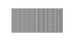
The line scan camera can only be calibrated in one direction—the scan direction. So, a pattern of parallel bars as shown in Figure 20 is sufficient. An array of dots or a checkerboard offers no advantage and can be more problematic.
Longitudinal calibration is often done indirectly by knowing how the camera is triggered relative to the motion. For example, a rotary encoder used to trigger the line scan camera is attached to a nose roller of a conveyor belt so the encoder pulses happen at a known interval of motion. If this timing is not available or if it is not sufficiently accurate, it is sometimes possible to put two or more marks at a known spacing on a conveyor belt passing through the camera’s view. Examination of the image (a series of sequential scans) from the camera, allows the determination of the spacing of the scan lines on the conveyor.
Related: Choosing a Line Scan Camera for Web Inspection Applications
Selecting a Lens
Most often, line scan cameras present challenges in lens selection. One challenge is the length of the image sensor that is often much longer than the size of area scan cameras. For example, an 8,000-element line-scan sensor can have a length of 57.7 mm compared with a high-resolution area camera that may have an image sensor diagonal of 20 mm. Another challenge is the relatively short focal length often needed with line scan imaging. Short focal length lenses typically have higher distortion and provide poorer relative illumination than longer focal length lenses. Fortunately, lens suppliers are providing lenses specifically designed for line scan cameras to address these challenges.
Related: Lens Selection—Keep the Entire System in Mind
Illumination
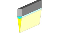
Line scan imaging is known to require much more intense illumination than typical area scan imaging primarily due to its shorter exposure time. This is true when considering intensity, or energy density. However, line-scan imaging does not necessarily require more light energy. In fact, because line scan image sensors have close to 100% fill factor, they are typically more sensitive than most area scan image sensors. Line scan imaging requires the energy to be concentrated into a thin line with a line light like that shown in Figure 21.
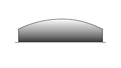
Line scan imaging is known for uneven exposure along the scan line. (See Figure 22.) This is not a variation in sensitivity along the image sensor. Some of the unevenness can be attributed to the relative illumination of the lens. Most of the unevenness is due to the difference in illumination along the line of view. A point in the middle of the line of view is typically getting light spanning from left to right and tends to reflect this light most strongly directly up into the camera’s lens. A point at the end, say the right end, gets light from the left to directly above, but none from the right. It tends to direct much of the reflected light energy further to the right and away from the camera’s lens. Because this is common, many line scan cameras offer built-in programmable flat field correction to provide a gain correction for each pixel in the scan line.
Related: Lighting for Line Scan Imaging
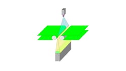
Because of the unique imaging structure of line scan imaging, back lighting, when required, is still achievable. For web products, this is usually not a common challenge. For discrete parts, the most common backlighting scheme is a conveyor with a narrow break allowing the back light to illuminate the camera’s line of view as shown in Figure 23.
Time Delay Integration (TDI)
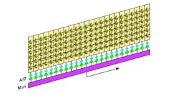
A widely used approach to increasing the effective sensitivity of a line scan image sensor is to incorporate a number of parallel and adjacent rows of pixels. After each exposure interval, the photo generated charge is moved from one row to the next. (See Figure 24.) Only the last row is read out. The benefit of TDI imagers is the total time to accumulate the photo generated charge is the exposure time multiplied by the number of rows. Typical TDI image sensors have from 64 to 256 rows.
TDI imaging demands precise coordination of part motion and shifting of the charge from row to row. Otherwise, the image will be smeared. Also, most TDI image sensors cannot have a programmable exposure time; so, motion must be very constant.
There is no line-scan specific interface. Line scan cameras use a frame grabber or, in the case of GigE Vision, there is a software process that roughly mimics a frame grabber.
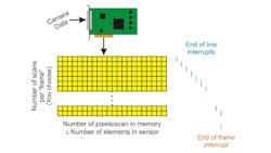
A frame grabber is designed to acquire an image (frame) from an area camera. It expects to receive a certain number of rows and columns of pixels from the camera or end-of-line and end-of-frame signals from the camera. Line scan cameras have a predetermined number of columns of pixels per scan and can provide an end-of-line signal. Line scan cameras do not have any sense or limitation on the number of rows to supply and cannot provide an end-of-frame signal.
However, the processor is looking for an interrupt signal to identify the data present for processing. If the end-of-line signal is used to generate the interrupt, interrupts will be very frequent, consuming a large portion of CPU resources. It is more practical to program the frame grabber to provide an interrupt after acquiring a predetermined number of scan lines. Thus, there is a virtual frame as shown in Figure 25. The number of lines in the frame is up to the vision system designer to determine based on requirements and computing resources.
Related: Line Scan Cameras Check the Quality of Laser Cut Parts
Challenges
Output Timing
For sorting operations and similar functions where the output must be timed relative to a certain scan line—for instance, the scan line at the center of an object—the variation in time to process the image becomes a significant factor.
In these cases, the scan number must be carried along with the image data to be included with the result of image processing. The delay between the scan on the object and the activation of the output can be calculated based on the scan number of the input and the scan number associated with the result.
Processing Timing
The time to process image data is variable depending on the complexity of the image data and other computational processes sharing the CPU. The biggest risk, for product in continuous motion, is the processor falling so far behind the current scan it cannot reasonably catch up.
The probability of this happening can only be determined with reasonable certainty through testing.
Detection of Processing Overload
For continuous process streams, there is always the possibility, however remote, for the image processing to fail to keep up with the input stream. Usually, this is the result of problems with the product itself causing significantly more image processing burden than expected. The image processing program should be designed to detect the overload and handle it in some acceptable way.
Summary
Line scan cameras are well suited to addressing a range of common machine vision applications. There are line scan solutions for monochrome, color, SWIR, and even hyperspectral imaging.
Line scan imaging needs special attention to triggering the exposure of each scan line. Lighting must be concentrated on the line of view for best exposure and adequate scanning speed. Processing line-scan data requires selecting the virtual frame size, addressing any risk of processing lagging the input, and addressing how to time the output of the image processing.
Read Part 1 of this series on line scan imaging HERE.
About the Author

Perry West
Founder and President
Perry C. West is founder and president of Automated Vision Systems, Inc., a leading consulting firm in the field of machine vision. His machine vision experience spans more than 30 years and includes system design and development, software development of both general purpose and application specific software packages, optical engineering for both lighting and imaging, camera and interface design, education and training, manufacturing management, engineering management, and marketing studies. He earned his BSEE at the University of California at Berkeley, and is a past President of the Machine Vision Association of SME Among his awards are the MVA/SME Chairman’s Award for 1990, and the 2003 Automated Imaging Association’s annual Achievement Award.
