Vehicle manufacturer uses vision system to identify specific vehicle criteria
A vehicle manufacturer sought a vision system for its plant that could check different criteria in automobile production according to specific types. Assembly line operators had been checking these criteria, and there were differences in how the criteria were evaluated depending on the particular shift. In addition, operators found it strenuous to maintain the same level of evaluation at the end of the shift.
To relieve the burden on operators, the vehicle manufacturer required a system that would first read a bar code to determine the vehicle type. Then, the system would perform type-specific presence checks, measurements, and pattern recognitions. The system would answer several questions, including:
- Are all screws present?
- Are the cables fitted with the correct color?
- Are the plugs connected correctly?
- What is the position of a certain flange in relation to the rest of the vehicle?
- How are individually installed components aligned?
- Is the right component installed?
The vehicle manufacturer chose Quality Automation (Stolberg, Germany; www.quality-automation.de) to design the vision system that would address these requirements.
Quality Automation’s modular, expandable machine vision systems can be used to individually implement machine vision requirements. Industrial cameras and machine vision software from MATRIX VISION (Oppenweiler, Germany; www.matrix-vision.com) act as the platform for Quality Automation’s PC-based machine vision systems. The industrial cameras are programmed or parameterized using browser-based machine vision software. Thanks to a user-friendly interface, maintenance engineers can independently maintain the system after a short amount of training. If the machine vision system is integrated in the company network, the browser-based software also provides flexible access to the industrial cameras from any location. Remote maintenance is also possible.
Quality Automation examined this situation and produced two machine vision systems with the vehicle manufacturer. The first system, for a presence check, comprises six industrial cameras, while the second system, for measurements and pattern detections, is equipped with nine industrial cameras. The six-camera system detects whether features are present and will performs pattern detection to detect if the features are installed correctly. The nine-camera system detects if features are installed correctly.
Every camera records a characteristic that must be tested. The factory’s master control system sends both machine vision systems the information according to which vehicle type is to be tested. The necessary limit values are also sent to the machine vision systems. When the system carries out a measurement to check a criterion, the limits from the specification of the vehicle data are transferred from the higher-level system. The system then receives, for example, max: 16.5 mm and min: 15.5 mm. The machine vision system is calibrated and can measure in real dimensions. For example, when the system checks the presence of a component, this is taught manually to the system by the programmer either via comparison with a reference image (pattern search) or via a simple vision tool such as an edge detection.
The limit values are fixed. If a limit value is exceeded for a feature, this feature is marked as faulty. This is included in the algorithms of the machine vision systems. The limit values are transmitted from the higher-level system to the machine vison systems. This way it is easy to make changes to the limits.
The characteristics are checked by the machine vision systems, and the results are visualized by a control monitor at the test positions. If the system finds an error, the operator is informed, and production cannot continue. The operator then has the option of solving the problem and then starting the machine vision systems manually. If the system does not find any errors after this, production can continue normally. If the system finds an error again, the operator can classify the car as bad. After that the production can continue normally. In both cases, the result of the machine vision system (good car, bad car with cause of error) is sent to a higher-level system. “The systems check the correct assembly of the vehicles,” says Michael Lambertz, Quality Automation Software Engineer. “Most components are assembled by humans by hand. Errors can occur here. The systems check whether components have been mounted in the correct orientation, whether components are present, and whether the components matching the current vehicle type have been mounted.”
Lambertz continues, “The systems primarily increase accuracy and eliminate human error. The systems can examine the inspection characteristics more accurately than would be possible with the human eye. And, the systems always work the same way. There are no deviations due to changing employees or employees getting tired.”
The detected data in the machine vision systems and the error patterns are stored in a master system. The tested criteria are fully documented, and errors can also still be analyzed long after a vehicle has left the assembly line. The scalability of the machine vision system also enables the vehicle manufacturer to extend quality assurance to other areas at a later date. The extension is not only limited to the number of used industrial cameras. The system integrator has up to 80,000 different industrial camera combinations because of the large number of different sensors, filters, lens holders, interfaces, housing types, and protection classes in the MATRIX VISION module.
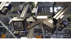
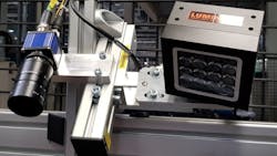
Both systems, the six-camera system and the nine-camera system, work the same. The only difference is what features they are inspecting. “With a fixed cycle time, new vehicles come to the position of the camera system,” says Lambertz. “The cameras and lights hang above and to the side of the vehicle. When the new vehicle is in position, the cameras take images one after the other—sometimes simultaneously—and evaluate the inspection characteristics. The results are displayed as an image with the measured value and status on a monitor located directly next to the production line near the cameras. If the image processing system detects an error, the operator at the line can correct the error. Afterward, he can restart the image acquisition manually to check whether he has corrected the error correctly.” Communication between the cameras and the industrial PC is via Ethernet.
The cameras used by the two systems are from MATRIX VISION. They include the mvBlueCOUGAR-109bG-POE-I Gigabit Ethernet Camera 4112 × 2176 (grayscale), the mvBlueCOUGAR-104iG-POE-I Gigabit Ethernet Camera 2064 × 1544 (grayscale), and the mvBlueCOUGAR-104iC-POE-I Gigabit Ethernet Camera 2064 × 1544 (color). They are compliant with the GigE Vision® and GenICam™ image processing standards. The cameras are optimized for both machine vision tasks, relying on high frame rates combined with low latency image transport. Hardware preprocessing is on-board (FPGA) to reduce the CPU load of the host. Image memory is 64 MB.
The cameras employ lenses from Vision & Control (Suhl, Thuringia, Germany; www.vision-control.com). The VCN 1.9/35 entocentric lens is a manually adjustable standard lens with fixed focal length of 35 mm for C and CS mount cameras. Lens length is 28 mm with a 30 mm diameter. It weighs 50 g. The VCN 1.4/8 entocentric lens has a fixed focal length of 8 mm. Lens length is 30 mm with a 30 mm diameter. It weighs 55 g.
Illumination is from Lumimax (Suhl, Germany; www.iim-ag.com) and Quality Automation. Lumimax lighting includes the LQ100FL-14-IR850-750, the LQ100-10-W, and the LG1010-DL-IR850 area flood lights.
The LQ100FL-14-IR850-750 provides infrared illumination with an 850-nm wavelength. Light area dimension is 65 mm by 65 mm. It uses high-power LEDs and weighs 1000 g. The LQ100-10-W provides white illumination using high-power LEDs in the 6000 K wavelength. Light area dimension is 65 mm by 65 mm, and it weighs 1000 g. The LG1010-DL-IR850 provides infrared illumination in the 850-nm wavelength using high-power LEDs and LightGuide. Light area dimensions are 100 mm by 100 mm. The unit weighs 550 g. “The operators should be disturbed as little as possible by the image processing system,” says Lambertz. “Therefore, infrared illumination was used for all cameras, with the exception of the color camera. In addition, space was very limited at two locations, so Quality Automation developed and manufactured two extra-flat illuminators itself.”
Software packages for the application include MATRIX VISION’s mvIMPACT Acquire for the recording and analysis of the camera images and mvIMPACT Configuration Studio for the parameterization of the cameras.
Lambertz states that Quality Automation chose the systems because of the flexible expansion possibilities and the large selection of camera models. He adds that the software is simple and clearly designed so that the maintenance staff can be trained quickly and can manage the system independently. The system has been running stably since installation. The operators on the line now no longer have to check the defect features themselves as the vision system takes care of this. No changes had to be made after the installation, and Quality Automation plans to expand the image processing system in the future for new vehicle types.
About the Author
Chris Mc Loone
Editor in Chief
Former Editor in Chief Chris Mc Loone joined the Vision Systems Design team as editor in chief in 2021. Chris has been in B2B media for over 25 years. During his tenure at VSD, he covered machine vision and imaging from numerous angles, including application stories, technology trends, industry news, market updates, and new products.


