Machine vision system detects antenna trace defects on automotive glass
Line scan camera improves vision system resolution to identify 0.25 mm holes, voids, and breaks in screen-printed antenna traces.
When screen-printing silver ink antennas onto automotive glass, clogged or stretched screens can cause partial breaks, full breaks, or thinning of the trace. Sometimes there isn’t enough ink, or there are bubbles in the ink, which may lead to defects.
If defects on antenna traces on automotive glass make it through a production process unnoticed, it leads to decreased or non-operational antennas, as well as lost time and production costs. Furthermore, due to the nature of the screen-printing process, when the system begins detecting “bad” parts, the manufacturer knows that often the entire lot is likely flawed.
Identifying such defects before products are shipped out is imperative and accurate inspection of glass proves a difficult challenge. Tasked with tackling this issue for one of largest glass manufacturing companies in North America was machine vision systems integration company Performance Automation (Cincinnati, OH, USA; www.pavision.net), which developed a system based on a contact image sensor (CIS) line scan camera with integrated illumination and custom software to identify potential defects.
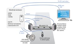
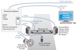
Figure 1. Glass is taken from two separate pallets and placed onto a conveyor by two Fanuc robots, and a SICK incremental coder tracks the motion as the glass moves through the sensors field of view. A photoeye from Omron detects the presence of glass and triggers image acquisition from the Mitsubishi line scan camera.
In the previous system, explains Performance Automation Vision Engineering Manager Lowell Cady, the manufacturer wouldn’t have been able to detect breaks that were 0.25 mm or smaller, so they might have had an entire day’s worth of production that wouldn’t function as intended.
In the system (Figure 1), the CIS line scan camera feeds high-resolution images to proprietary software that performs defect detection. A monochrome KD6R926MX camera from Mitsubishi Electric Corporation (Tokyo, Japan; www.mitsubishielectric.com) captures images at 600 dpi. Based on a 21,888-pixel line scan image sensor that achieves a scan speed of up to 43 kHz, the camera features a 929.6 mm scan width, Camera Link interface, a white LED array, and a design offering 12-mm aligned CIS sensor chips.
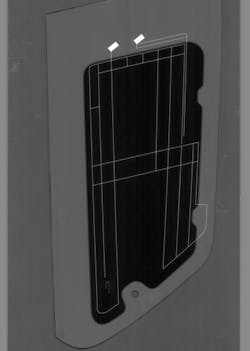
To set up the inspection process, an operator sets a properly-built part on the conveyor and selects the “Acquire Golden Image” command using a human-machine interface (HMI) with a grid-based menu system. This image later defines the inspection process. (Figure 2.)
Figure 2.To set up the inspection process, an operator sets a properly-built part on the conveyor and selects the “Acquire Golden Image” command using a human-machine interface (HMI) with a grid-based menu system. This image later defines the inspection process.
Different thicknesses of glass run on the inspection line and the camera must be 12 mm from the surface being inspected. To accomplish this, the team installed two compact linear actuators from Oriental Motor (Tokyo, Japan; www.orientalmotor.com). These linear actuators move the camera as much as 1 in. (25 mm), allowing it to keep focus. The operator selects the model of glass to run, and the first step in the process involves changing the elevation of the camera with the motors and setting it to the right focal distance.
Glass is taken from two separate pallets and placed onto a conveyor by two Fanuc (Rochester Hills, MI, USA; www.fanucamerica.com) robots, and a SICK (Waldkirch, Germany; www.sick.com) DFS60 programmable, incremental encoder is used to track the motion as the glass moves through the sensor’s field of view. Feedback is used to dynamically adjust the line-by-line image build up. This is important, according to Cady, because the application requires square pixels to minimize compression or stretching artifacts within the image.
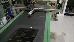
A photo eye from Omron (Kyoto, Japan; www.omron.com) detects the presence of glass and triggers image acquisition. Glass travels completely underneath the camera (Figure 3) and images acquired are transferred to a Windows 10-based Dell (Round Rock, TX, USA; www.dell.com) PC via a Camera Link frame grabber from National Instruments (NI; Austin, TX, USA; www.ni.com). Next, software utilizing LabVIEW and vision acquisition drivers from NI analyzes the image data.
Figure 3. Antenna traces on automotive glass are inspected as they pass under the field of view of the line scan camera from Mitsubishi Electric.
“Because a single image captured by the system ends up being about 250 MPixels in size, images are scaled down by the CPU so that pattern searches and operations are sped up,” says Cady.
Once glass is detected in a scaled image, coordinates are scaled back up to show where the tools for the traces must go in the larger image. For centroid and Hough line detection, images are scaled to 1/10th of the original size, and for pattern matches, 1/4th of the original. Minimum defect size depends on the type of defect, says Cady.
“If it is a break in the line, we can detect down to 3 pixels wide. If it’s air bubbles, this can be detected down to an area of 3 x 3 pixels, and if it’s a chip in the line where the line is getting narrower, the system can detect down to 12 pixels wide. If it gets narrower by more than 4 pixels, then we are going to detect it,” he says.
Intersections of the trace are automatically identified, and a pattern matching algorithm inspects and masks the identified intersections. Some intersections are 90°, others are Y shaped, so each type of intersection required its own pattern match.
“The previous version uses railroad ties to find the edges from the outside in, but the new method centers the path by pattern match, followed by a radial search for left and right edges closest to the pattern center,” says Cady.
Masking out the intersections results in a series of line segments, and the same algorithm is used to inspect all line segments.
“A test of aligning the path model to the glass using corner points to create a homography matrix, instead of a pattern match method, was not as initially robust as I thought it would be, so we used pattern match algorithms,” says Cady. “However, we were not ready to give up on using features to create the homography matrix, as we hoped the paths could all be transformed from just one homography matrix.”
The features, however, didn’t yield a reliable result, even after pre-filtering them. To improve this, the centroid of the glass was found via the convex hull of the lines, allowing the model to shift onto the glass location.
The rotation of the model is found by detecting a dominant line with a Hough transform. Once location and rotation are known, the accuracy of the feature inspection is improved by pattern matching. Each intersection feature has its own template that was extracted from the model and the template can be masked, cropped, and re-centered in an editor. Pattern matches are run in eight parallel loops on the PC and the results of all eight are found in 5-10 ms. Scores obtained were very good—all more than 900— and the paths used the results of the pattern match to align more accurately with the glass.
Acquisition takes approximately two seconds for each piece of glass and inspection takes about three seconds, for a full cycle time of about five seconds for each piece of glass, according to Cady.
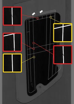
Figure 4.If the software detects a defect or anomaly, the operator gets a ‘light’ graphic indicator through the HMI display, and an overlay marks the location of the defect, allowing the operator to zoom in for further inspection. Red shows failures, while yellow shows warnings.
If the software detects a defect, the operator gets a ‘light’ graphic indicator on the HMI display and an overlay marks the location of the defect, allowing the operator to zoom in for further inspection (Figure 4). If the operator is away from the system when a defect is found, a third Fanuc robot equipped with a padded vacuum gripper—to avoid scratching the glass—removes the glass and puts it into an accumulator. Glass that passes inspection is moved into the furnace. This is possible because of the system’s I/O card, which sends pass/fail signals to a Mitsubishi Electric programmable logic controller, which controls the conveyor and signals the robots to start each operation.
Another issue inherent with the system is that glass often sticks to untextured surfaces, making it difficult for the robot to pick it off the conveyor. To deal with this, the conveyor surface has a 1 to 2 mm high, finger-like texture.
“We inadvertently hit a sweet spot because the camera’s depth of field [about 1 mm] is shallow, so any of the detail on the texture of the conveyor does not have enough contrast to affect the overall inspection,” says Cady.
Additionally, instead of just making yes or no determinations, the manufacturer uses a sliding scale for scoring different features in finite amounts.
“For example, if there is a bubble that is under the threshold where it matters for quality purposes, the operator can set the system so that you’d need to have a lot of bubbles within a 2 mm area for it to fail. The one feature that cannot be changed is, if there is a crack all the way through the line, it fails every time.”
This new inspection system is finding previously unseen defects and provides data to inform future antenna trace printing processes to avoid failures, says Gene Kalhorn, Vice President and CEO of Performance Automation.
“Defects detected by the machine vision system enable the automotive glass manufacturer to look at trends in the types of failures and make appropriate changes in the screen-printing process before it becomes a major problem,” says Kalhorn. “They can also use the machine vision system as a tool to see whether the engineering fixes are really making enough of a change or not.”
About the Author

James Carroll
Former VSD Editor James Carroll joined the team 2013. Carroll covered machine vision and imaging from numerous angles, including application stories, industry news, market updates, and new products. In addition to writing and editing articles, Carroll managed the Innovators Awards program and webcasts.
