Robots and vision place engine-valve plates
Andrew Wilson, Editor, andyw@pennwell.com
In automotive assembly, precision valve-body assembly ensures that correct hydraulic pressure will be directed to devices such as clutches, which drive or lock gears into place. To automatically assemble these valve bodies requires correctly placing numerous components within them and tightening them into place. One component is the valve plate, four of which must be oriented in the correct position, placed onto the valve bodies, and screwed into place.
“Unfortunately,” says Tim Patterson, engineering manager at SELCO Engineering (Indianapolis, IN, USA; www.selcoeng.com), “these valve plates are not cylindrical and must be checked for proper orientation before they are placed in the valve body.” To do this, Patterson and his colleagues have developed an automated assembly system that combines robotics and vision to ensure the correct orientation and placement of these valves. Once correctly placed, the system automatically tightens the plates into position using two screws per plate.
To place the four valve plates simultaneously, a set of four positioning shafts holds multiple plates in position. As each valve body is indexed along a conveyor, a Camco Cambot from Industrial Motion Control (Wheeling, IL, USA; www.camcoindex.com), fitted with four pick-and-place actuators, is linearly staged over the four valve plates.
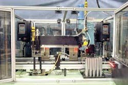
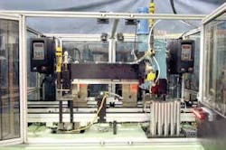
To check for correct orientation of valve plates, SELCO Engineering has developed a robotic system that inspects each part, places it into the valve body, and then screws the parts into place (on left). To check for proper orientation, a smart sensor is used to locate a dimple located at the top of each part.
Mounted with a 640 × 480, 60-frames/s monochrome In-Sight 5100 smart sensor from Cognex (Natick, MA, USA; www.cognex.com), the robot individually positions the camera over each of the four plates to check their orientation. “Because the parts are shiny,” says Patterson, “direct on-axis illumination could not be used.”
A linear LDL Series red LED array from CCS (Waltham, MA, USA; www.ccs-inc.co.jp) was placed off-axis to illuminate the surface of the plates (see image on p. 16). By placing the camera at 45° to the plates, their surfaces could be properly illuminated.
Each part is marked with screw holes located approximately at the center, and a dimple is used to locate the proper orientation of the part. Cognex In-Sight software running on the 5100 checks for the presence of this dimple. PatFind, the standard In-Sight object-location tool, locates the presence of this feature and is programmed using In-Sight spreadsheet-based program.
“Once the dimple mark is located,” says Patterson, “the robot is indexed to check for the correct orientation of the remaining three parts located in the positioning shafts.” Should all four parts pass this inspection, the In-Sight 5100 instructs a PLC from Allen-Bradley (Milwaukee, WI, USA; www.ab.com) to position the Camco Cambot to place the valve plates within the valve body.
“Should any of the vision inspections fail,” says Patterson, “the robot places all four parts into a reject chute, where they can be recycled.” This process is repeated until four parts in a known good orientation are placed in the housing.
After placing the parts in a correct orientation, each valve body is then indexed to a single screwdriver station, where all four parts are fastened. Finished parts are then moved to further assembly stations where other parts are added.

