CMOS camera checks automotive laser welds
To increase throughput and reliability of automotive parts, a machine-vision inspection system assesses weld-seam integrity.
By Andrew Wilson, Editor
Before automobile doors or hoods can be pressed, they must be shaped into a specific form using a number of individual metal sheets or tubes known as "tailored" and "tubular" blanks. After these blanks are welded together, each individual weld must be rigorously checked before the metal can be pressed.
"Welding tailored blanks is one of the most important applications of laser welding in the automotive industry," says Daniel Wildmann, managing director of the Soudronic Automotive business unit. "This year worldwide tailored-blank production will reach 180 million parts per year and will grow to 250 million parts over the next few years," he says.
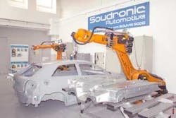
Visual checks of these welds by operators are no longer cost-effective or sufficiently reliable. Therefore, many automotive suppliers are developing fully automated weld-inspection systems that provide inspection, analysis, reworking, and remote diagnostic capabilities. For example, the Automotive Division of Soudronic has developed the Souvis 5000, a PC-based machine-vision system that meets the needs of both large steel manufacturers and automotive manufacturers such as Volkswagen and Audi (see Fig. 1).
Designed to perform visual inspections during laser welding and laser brazing, the system analyzes the profile, structure, and pores of each weld with a single integrated sensor. "Deep-penetration welding is used in a number of applications in the automotive industry," says Wildmann, "and can result in both seam and random imperfections. While seam imperfections such as seam convexity or concavity can be seen over the length of the weld, random imperfections such as pores, seams, or cracks can appear anywhere along the weld."
ROBOT VISION
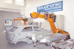
On automotive-production lines, large heavy panels must be inspected as they progress through individual assembly stations. Because the parts themselves cannot be oriented for visual inspection, image sensors must be designed to move freely around the object. To do this, Wildmann and his colleagues developed a networked-based robotically mounted vision system that illuminates and detects both seam and random imperfections (see Fig. 2).
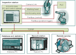
In addition to developing the integrated vision system, Soudronic had to ensure that the system could be integrated into factory-floor automation systems. The system design incorporates a robot from Kuka mounted with a machine-vision sensor that is controlled from a PC. This PC is then interfaced to programmable logic controllers (PLCs) on the factory floor, as well as other workstations over Ethernet.
Once a specific part is ready for inspection, the PLC instructs the robot to move the vision sensor over specific areas of the part. After the part is inspected, the results are stored in a statistical database, and, should any rework need to occur, specific areas on the workpiece are marked by an integrated marking head on the robot. These parts are then transferred to a rework station where further welding is performed. After parts pass inspection, they can be transferred to the next stage of the manufacturing process.
CMOS RULES
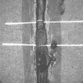
At the heart of the system is a specialized sensor that both illuminates and captures images from individual welds. Two kinds of lighting illuminate images of the welds. Two CW diode lasers mounted in the sensor head project structured light across the laser weld to detect whether each weld is convex or concave. By analyzing the profile of this line as the system moves along the weld, the system determines if excessive concavity exists over a specific seam length. To detect whether pores, seams, or cracks are present, the weld is simultaneously illuminated with a 20-µs white flashlight. This allows gray-scale information from a 10 × 10-mm area along the weld to be simultaneously captured with the structured laser information.
"One of the major problems that we needed to overcome in the design of the system," says Wildmann, "was the simultaneous capture of images of the very bright profile line and images of the low-light gray-scale image." Unfortunately, conventional CCD imagers were not up to the task. In such devices, the output signal is often a linear function of the input light intensity. Because of this, bright laser lines saturate the low-light gray-scale image, resulting in an unusable image.
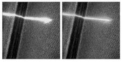
To overcome this problem, Soudronic uses the MV-D1024 camera from Photonfocus—a 2/3-in., 1024 × 1024-based CMOS camera that has the company's proprietary Linlog technology. Because the image sensor in the camera features a linear response at low light levels and a logarithmic response at high light levels, the camera can simultaneously capture gray-scale and laser triangulation images (see Fig. 3).
IMAGE ANALYSIS
After images are captured by the MV-D1024 they are transferred to the host PC with a microEnable III Camera Link frame grabber from Silicon Software. Using custom-developed software, the profile of the laser line is analyzed for both direction and structure. This provides information such as the width of the seam and whether the laser weld is convex or concave. To analyze the texture of the weld, features are computed based on its gradient and direction.
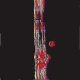
"By extracting a few features of the profile and the gray-scale image," says Wildmann, "quality and weld smoothness can be determined." Significantly changing numbers indicate a local weld imperfection, a lack of penetration due to plasma shielding, or an expulsion of the weld pool due to the evaporation of the coating material (see Fig. 4).
null
To perform pore analysis of the weld area, the gray-scale information is used to compute defects that may be as small as 100 µm. Specific blob-feature sizes are computed and compared against known user-defined porosity data. Should a defect be detected along the seam, the part is rejected or transferred to a rework station and repaired before it can be shipped to the customer.
Wildmann says, "Because the PC-based Souvis 5000 system is integrated in an Ethernet environment, other features such as statistical data analysis, rework stations, and remote servicing can be easily integrated into the system." The rework station, networked to the Souvis system, displays the image of the part as it is captured from the sensor. By annotating color overlay data to the image, the operator can see the weld defects highlighted in red or green. Providing the rework operator with visual cues about the nature and type of each defect increases the productivity of the rework and, hence, the throughput of the production line.
features, advantanges, benefits
Soudronic developed a custom statistical-analysis package using Microsoft C++ for Audi's A3 laser-brazed roof. With this package running on a remote Ethernet-based PC, users can analyze the number, types, and sizes of defects on each autobody, where such defects occur, and at which times in the production welding process these defects occurred.
"In this way, the systems operator can evaluate each shift and understand better how the laser-brazing process is performing," says Daniel Wildmann of Soudronic Automotive. Ethernet-based networking also allows the Souvis 5000 system to be remotely monitored once deployed. This permits engineers at Soudronic Automotive to remotely check system parameters in real time. By downloading images from the embedded sensor, the camera parameters and functions can be set, reset, or monitored, so that remote system diagnostics can be performed.
According to Audi, the system has already proved successful. In addition to reducing inspection times, the system has increased throughput; accuracy of the seam data acquired allows the system to qualify the seam defects specified in ISO 13919-1, Quality Standard B.
Company Info
Audi, Ingolstadt, Germany www.audi.com
Kuka, Augsburg, Germany www.kuka-roboter.de
Photonfocus, Lachen, Switzerland www.photonfocus.com
Silicon Software, Mannheim, Germany www.silicon-software.com
Soudronic Automotive, Neftenbach, Switzerland www.soudronic.com
Volkswagen, Wolfsburg, Germany www.volkswagen.de
