Vision-guided robots place heavy engines
During automotive assembly, a vision-guided robot system recognizes the orientation of engine heads and picks and places them correctly on engine blocks.
By Andrew Wilson, Editor
In automotive power-train assembly lines, engine heads, which are delivered from manufacturing plants on large palettes (or dunnages), must be lifted onto engine blocks for the next assembly step. In the past, these heavy and often sharp-edged engine heads were manually lifted onto the blocks, an operation prone to worker injury—only one of several factors that demanded the automation of this repetitive, manually stressful, and hazardous operation. Surfaces on the engine heads must be as clean as possible and not contaminated by dust, dirt, and grease. Indeed, many automakers have traced several engine recalls to oil and coolant leaks stemming from this procedure.
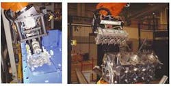
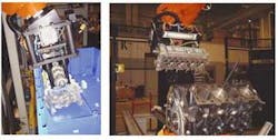
To automate this assembly process, Ford Motor Co. of Canada Ltd. (Oakville, ON, Canada) delivered a specific definition of the engine-lifting operation problem to ABB Canada (Brampton, ON, Canada). Engine heads produced at the Ford Motor Co. engine-manufacturing plant are packed into dunnages and shipped to assembly plants where they are mounted on engine blocks (see Fig. 1). During transit, these engine heads often move or tilt within their dunnages. Consequently, when they arrive at the assembly plant, engine heads are often found in different positions and orientations in the dunnages. However, a basic robotic part-acquisition system could not be used to locate, move, and place the engine heads onto the engine blocks. Furthermore, a conventional vision system that provides two-dimensional (2-D) part location offsets proved insufficient for this application.
Analysis demonstrated that a smart vision-guided robotic system is required. This system must be able compute the position and orientation of the engine heads in three-dimensional (3-D) space, that is, in x, y, and z coordinates and roll, pitch, and yaw rotation angles. After precisely locating the engine heads, the robot must then be directed to lift them from the dunnages and assemble (deck) them on the engine blocks. In addition, the vision system must recognize the part style being processed and warn the robot if the part is an incorrect style or is turned upside down. These capabilities would prevent expensive production damage and downtime trying to intercept the wrong part or a part in the wrong position.
Adding smarts
To add intelligence to the proposed vision-guided robotic system, ABB enlisted Braintech Canada (North Vancouver, BC, Canada), its partner in developing machine-vision and robotic-control applications. Braintech has achieved expertise in the development of robot-guidance systems using off-the-shelf hardware combined with its proprietary eVisionFactory (eVF) vision system.
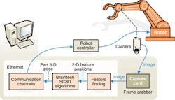
FIGURE 2. In the design of the vision-guided robot system for Ford Motor Co., Braintech integrated off-the-shelf hardware components. During operation, this vision system captures a single image, determines the 3-D coordinates of the engine head in terms of its orientation, and transmits this information to the robot controller.
For the Ford Motor system design, Braintech integrated a number of hardware components, including a camera, frame grabber, host CPU, and robot controller (see Fig. 2). During operation, an XC-ES50 CCD camera from Sony Electronics (Park Ridge, NJ, USA) is housed in a compact enclosure and inserted into a special robotic gripper supplied by Johann A. Krause Inc. (Auburn Hills, MI, USA).
High-frequency fluorescent lighting is added to the robot's end-effector to properly illuminate the associated parts. Before each pick-and-place cycle, the robot positions the camera over the area containing the power-train parts. The vision-guidance system then captures a single RS-170 image using a PCI-based Meteor frame grabber from Matrox Imaging (Dorval, QC, Canada) installed in a commercial 1-GHz Pentium PC.
"Single Camera 3D (SC3D) is a key component in eVF and is a technology developed by Braintech for determining the 3-D coordinates of rigid parts from a single video image," says Babak Habibi, president of Braintech. "This technology was developed in response to demands for a robust 3-D robot-guidance system for automotive parts-handling applications. Based on the use of a single CCD video camera, SC3D technology suits robotic-handling applications that involve precisely manufactured parts such as engine heads, intake manifolds, and automotive transmission housings and covers, among others," he adds.
After the images are captured, the eVF software determines the 3-D coordinates of the part in terms of its position (x, y, and z coordinates) and orientation (roll, pitch, and yaw angles). These values are transmitted to an ABB S4C Plus robot controller via an Ethernet connection. At this point, the robot controller uses the information to adjust the pose of its end-effector to match the 3-D coordinates of the part and then proceeds to intercept and grasp the part.
In extreme cases where the part is markedly tilted to one side, the vision-guidance system can perform two measurements (coarse and then fine) to achieve higher accuracy and reliability. The vision-guidance software running under eVF makes this decision automatically.
Software development
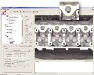
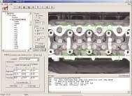
The Braintech eVF software platform is designed to allow development, runtime, and support of vision-guided robotic solutions to take place using the same interface. This platform leverages the power of several machine-vision and image-processing libraries, including the Matrox Imaging Library for basic machine-vision functions such as image filtering, region-of-interest selection, and feature finding. Functions from these libraries and Braintech's proprietary science (for example, SC3D) are wrapped into components that appear as graphical icons in eVF. In the design of the machine-vision/robotic-control system for Ford, Braintech used the software to analyze specific points on the engine head (see Fig. 3).
Using the logical workspace presented to the systems developer on the system screen, different machine-vision functions, including histogram equalization, blob analysis, and pattern-matching, can be chosen as part of a runtime script. For example, the system developer can highlight any component in the workspace, such as the pattern-matching component, to initiate a window within the development screen that allows the setting of specific attributes and settings of the given component, including the feature window size and the pixel search range. In this example, a specific area of the head-gasket surface has been highlighted.
Once a number of parameters have been set in this manner, the vision-guided robot system can be placed in automatic runtime mode (see Fig. 4). Then, the software cycles though the number of regions that have been programmed earlier, finds pretrained features, and makes measurements in both the x and y directions.
FIGURE 4. After several part parameters have been set, vision-guided robot system can be placed in an automatic runtime mode. Accordingly, the software cycles through the number of regions that have been programmed earlier, finds pre-trained features, and makes measurements in the x, y, and z directions and builds a psuedo-CAD file that accurately describes the orientation of the part.
Whereas these measurements can be made in the x-direction (right to left), they can be equally measured along the y-axis (top to bottom) later in the runtime cycle. "What is unique about the single-camera 3-D algorithm," says Habibi, "is that the system can take measurements in the x and y directions (that is, two-dimensional offsets) as inputs and compute from these the z (third dimension, or depth), as well as orientation angles of the part, all from a single image." Because the system has been trained with knowledge of the 3-D parameters of the part, 2-D data can be used in conjunction with known data to calculate measurements in the z direction, as well as the orientation angles.
Robot control
"SC3D technology mimics the human brain in determining the relationships between key points of the engine heads," says Habibi. "By training the system with known features, the angle of rotation of the part, for example, can then be computed. Basically, the eVF software builds a 3-D pseudo-CAD file from the results found by machine-vision analysis," he adds. This information is then sent in terms of x, y, and z, as well as rotation information, across an Ethernet interface to the ABB S4C Plus robot controller using a proprietary protocol.
When the robot controller receives this information, it instructs the ABB IRB 6400 robot to adjust its path and match the point where the part is located. If the part has moved in transit, for example, the robot can automatically adjust its co-ordinates in 3-D space, pick up the engine head from the dunnage, and place it on the engine block. "Accomplishing this task," says Habibi, "eliminates the need for manual lifting, reduces worker injury, decreases assembly time, and minimizes part-contamination hazards."
A major drawback in the design of previous robotic systems has been the need for recalibration. "Vision-guided robot systems need to determine x, y, z, and rotational position data from pixel data in terms of real dimensions, such as inches," says Habibi. "This can be a time-consuming process and, with downtime costs often running as high as $10,000 per minute, often very expensive." Accordingly, the eVF software has recently been equipped with an automatic calibration utility that instructs the robot to position the camera across vantage points around the part, locate known points, and autocalibrate the system for its next task. "Reducing the calibration time from 30 to 45 minutes to less than five minutes can often save automotive manufacturers thousands of dollars should the system need to be recalibrated," says Habibi.
Although Braintech's eVF software has been installed at more than 15 locations within Ford Motor Co., the company currently has no plans to directly retail its eVF software. Braintech has delivered multiple application runtime licenses of eVF to Marubeni Corp (Tokyo, Japan), who will identify customers and sell, install, and service the software in Japan.
Company Info
ABB Canada www.abb.com
Braintech Canada www.braintech.com
Ford Motor Co. of Canada Ltd. www.ford.ca
Johann A. Krause Inc. www.jakrause.com
Marubeni Corp www.marubeni.co.jp
Matrox Imaging www.matrox.com/imaging
Sony Electronics www.sony.com/videocameras
