Snapshots
Color vision system sorts blueberries
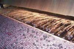
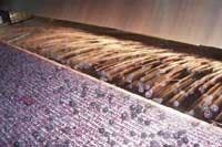
Inspecting 20,000 blueberries per second as they move along a conveyor at rates of up to 600 ft/min was the task delegated to Orus Integration (Boisbriand, QC, Canada; www.orusintegration.com). After berries are dumped onto a vibrating conveyor, they are transferred to another conveyor for high-speed sorting. To cover the 60-in. width of the conveyor, the Orus FL6500C system uses five Allied Vision Technologies (Stadtroda, Germany; www. alliedvisiontec.com) color Marlin 1394 cameras interfaced to three Meteor-II /1394 boards from Matrox (Dorval, QC, Canada; www.matrox.com).
Because the conveyor moves at a rate of 600 ft/min, the system must trigger the cameras every 2.5 in. with a 120-µs exposure. Using Matrox Imaging Library blob-analysis module allows blobs to be analyzed according to average hue, average brightness in the red layer, size, and roundness. Chunks of ice are rejected on color, and other foreign particles such as twigs or insects are rejected based on roundness and/or color. Unripe or overripe berries, or other types of fruit such as cranberries, are rejected based on color value or size.
After inspection, results are sent to an Omron (Schaumberg, IL, USA; oeiweb.omron.com) PLC via Ethernet cable to control an array of air jets that are positioned over the 14-in. gap between two conveyors. These jets direct the particles that fail inspection onto a reject plate.
Software checks cell phones
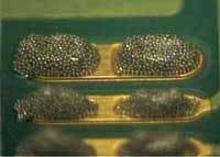
Ricardo dos Santos, a maintenance supervisor in the SMT department at LG Electronics (Sao Paulo, Brazil; us.lge.com) uses Image Pro Express 4.0 from Media Cybernetics (Silver Spring, MD, USA; www.mediacy.com) to monitor the production process of electronic components and cellular phones. He and his team measure the amount of solder paste that fixes components to the circuit boards and measure the size of the pads attaching the ICs to the boards, five times a day. If a pad is too large or too small, the configuration of the machine is changed to alter the amount of applied solder. “Before using Image Pro, we could not control the application of solder because of the very small size of the components,” dos Santos says.
He also uses the software to analyze defects in the machines used in cell-phone production. Because any damage in solder-paste nozzles can result in serious defects, all the nozzles are checked weekly and replaced if necessary. The 0.65-mm diameter of these parts makes it difficult to spot defects without image-analysis software.
Robot guidance speeds wheel-rim processing
To ensure precise assembly of aluminum wheel rims, bearing surfaces and mounting holes must be free of paint. This is achieved by automatically placing a Teflon plug in each mounting hole to mask it before it is painted. Bearing surfaces and drilled holes are kept free of paint by suctioning any coating powder from these parts of the rim before burn-in occurs.
Accomplishing such a task automatically is now possible using the ORIS (Object Recognition and Identification System), a machine-vision-based robotic-positioning system from ISRA Vision Systems (Darmstadt, Germany; www.isravision.com). This system computes data about the position, rotation, and type of rim to be processed. A camera with a ringlight then positions the robot’s plug dispenser. Acquired wheel data-the number of holes and diameter-are compared with a default value. A suction device on the robot, guided by a stationary-mounted camera based on a combination of acquired and provided wheel data, suctions coating powder.
Precise positioning of the wheel rims is necessary to automatically debur rims. The wheel rims are placed on a rotary indexing table and their translation and rotation mapped by a camera. The robot picks up the rim and positions it precisely in the deburring station.
Imaging rapidly analyses drugs
Unlike mapping systems, spectroscopic microscopes or bulk near-infrared (NIR) analyzers, NIR chemical imaging systems provide quantitative, qualitative, and spatial information in 2 min or less. But, because diffuse-reflectance NIR data often exhibit wavelength-dependent differences in scattering of reflected light, spectral artifacts are often generated that cloud interpretation and quantization.
To overcome these limitations, systems such as the MatrixNIR from Spectral Dimensions (Olney, MD, USA; www.spectraldimensions.com) include multivariate data-preprocessing algorithms such as multiplicative scatter correction (MSC) that correct for such artifacts. By integrating spectral and spatial information with ISys data-visualization software, a single step can remove spectral artifacts with techniques such as MSC. Results of such analysis can be impressive as can be seen by comparing NIR reflectance images of a tablet before and after MSC. Principal component analysis scores of an over-the-counter pain medication computed from a NIR reflectance image data set shows active pharmaceutical ingredient (API) as white particles. The intensity at each pixel relates to membership in the API class and maps directly to drug concentration.
Medical imaging system improves diagnosis
Doctors at cardiology labs use intravascular ultrasound catheters to determine the types and sizes of lesions in patients’ coronary arteries. After a catheter is inserted into the femoral artery, through the heart, and into coronary arteries, lesions are imaged using a beam-forming transducer.
Volcano Theraputics (Rancho Cordova, CA, USA; www.volcanotherapeutics.com) uses this technology in its InVision Gold intravascular ultrasound system. The design comprises an in-house-developed imaging engine and a PC-based user interface storage and data-retrieval system that incorporates the Viper-RGB and Viper-Digital frame grabbers from Coreco Imaging (St.-Laurent, QC, Canada; www.imaging.com).
Images acquired by a transducer inserted into a patient’s arteries are transmitted to the InVision Gold imaging engine that performs A/D conversion, beam forming, reconstruction, color flow, and digital vector processing. A scan-converter board connected to a VME/PCI bridge board transfers data processed by the engine into a Pentium-based PC. Still images and up to 9 min of video can be viewed on a fluoroscopy monitor, saved to a hard drive, archived to a CD-ROM, or transferred to a remote server via a DICOM network.

