Vision-system performance
Vision-system performance
By Mike Leary and John Bush
Matching an application to readily available machine-vision systems involves considerable risk. If you try to stretch a PC-based system to its limits, you risk failing to meet your throughput requirements. If you choose a high-end bus-based system, you may use only a portion of the performance you paid for.
PC-hosted systems offer modest performance, are inexpensive ($10,000 - $15,000), and can be integrated with diverse off-the-shelf hardware and software. They also offer easy-to-use software tools that make development feasible for systems integrators and in-house design teams. Bus-based systems, on the other hand, offer top performance but are expensive and require considerable development skill. Between the two worlds lies a void that system providers have only recently begun to fill.
At the low end of the PC performance spectrum are Pentium-based systems equipped with dumb frame grabbers. In such systems the host handles both system control and image processing. For a step up in performance, users also can augment the Pentium`s processing power with image-processing boards based on digital signal processors (DSPs), application-specific integrated circuits (ASICs), and other coprocessors. These cards may come equipped with comprehensive software libraries, driver support for standard camera interfaces, and even industrial control interfaces. Fully configured and tested off-the-shelf systems are also available from several vendors.
PCs are low-cost and simple
Most of the low-end imaging add-in cards available for PCs are Industry Standard Architecture (ISA) based, but many vendors are moving to Peripheral Component Interconnect (PCI) to address the ISA Bus` bandwidth limitations. PC-based systems typically use standard RS-170 or CCIR cameras, which are inexpensive and easy to use. Other cameras can be used with PC-based systems, but they can require custom drivers to control parameters such as pixel clocks and integration times. Using nonstandard cameras also risks compatibility problems.
Software for PC-based systems is almost universally Windows-based, with 32-bit versions proliferating because of Windows NT. Windows NT is a stable, reliable operating system that is taking over the industrial PC world. Its main drawback is a lack of deterministic real-time response, which is a requirement for many applications.
Because of its ease of use, Visual Basic is a favorite among man-machine-interface (MMI) developers. But MMIs developed for higher-end systems are often coded in more robust and efficient languages such as C and C++. Algorithm developers also prefer to work in C/C++, using point-and-click graphical programming systems and leveraging off-the-shelf machine-vision libraries.
The primary weakness of PC-based systems that rely on the host processor for imaging is low performance. When working with a standard 512 ¥ 512 ¥ 8-bit image, achieving useful frame rates for even the most basic operations is difficult. For example, when executing a benchmark program comprising erosion, dilation, thresholding, image subtraction, and 3 ¥ 3 convolution operations, a host-based system can require several seconds to process each frame.
One way to boost the image-processing capabilities of the PC is to add a C40-based ISA card, such as Cyclops from Ariel (Cranbury, NJ). With such a card, system integrators can boost performance three to four times, reducing the typical frame-processing time to about 0.75 s. Multiprocessor C40-based ISA cards can boost performance still further.
Bus-based systems boost performance
For significantly higher performance than PC-based systems can offer, designers may have no other option than to consider a high-end bus-based system. Bus-based systems typically use multiple control and image-processing boards connected over a VMEbus or proprietary backplane. Usually, a separate host acts as a server for one or more imaging subsystems, providing the user interface and maintaining user databases. The subsystems` control board, which may use any number of high-end RISC or CISC processors, handles image-processing-board configuration and controls the image-capture board. Due to the real-time constraints of many high-end applications, these controllers often run a deterministic, real-time operating system such as VxWorks from Wind River Systems (Alameda, CA), pSOS from Integrated Systems (San Jose, CA), or LynxOS from Lynx Real-Time Systems (San Jose, CA). These manage real-time tasks that control and synchronize multiple imaging boards.
Data-processing boards used in bus-based systems use employ a configurable pipeline of DSPs and/or ASICs, massively parallel architectures, or hardwired implementations of common algorithms. Bus-based image-capture boards work with a range of cameras, including line-scan and time-delay-integration types. Bus-based systems can not only handle far more complex algorithms than their PC counterparts, but can process them at much higher frame rates. VME boards from Datacube (Danvers, MA) can operate at a rate of 20 Mpixel/s. That is fast enough to process large images at more than twice the standard frame rate. With today`s high-end imaging boards, VMEbus data-transfer rates, rather than board-level performance, is often the main bottleneck.
Bus-based system development can be expensive. Equipment and engineering costs may run from $250,000 to $3 million. Moreover, development takes a long time and requires considerable expertise. A major risk in developing such systems is underestimating the project`s difficulty. To minimize such risks and reduce development time, therefore, systems integrators should have experience in both machine vision and the specific application.
Mid-range solutions fill the gap
Between low-end PC-based and high-end bus-based systems lies a performance gulf spanning two orders of performance magnitude. Increasing PC performance has helped shrink the gap, but many vision-system applications still fall between the two extremes. But now, a new system class is emerging that helps bridge the gap. Systems in this class use a PCI-based PC as host and imaging cards based on Texas Instruments (Dallas, TX) TMS32C80 processor.
The C80 is tailor-made for image-processing applications, combining a RISC CPU with four DSPs. While the four DSPs handle core imaging operations, the CPU serves as the controller, boosting system performance and minimizing bus traffic by offloading the host PC of decision-making responsibilities.
Such C80/PCI-based systems provide a performance boost while still taking advantage of the PC`s ease of use and third-party hardware/software support. And they do so for a modest price tag, with equipment costs ranging from $20,000 to $55,000, depending on the number of `C80 boards used. Library and tool support still lags behind that of ISA bus solutions, but that will change as the industry moves from ISA to PCI.
PC system inspects printed-circuit boards
Even an unassisted PC can provide sufficient performance to handle many basic machine-vision applications involving still or slowly moving images. Such applications include simple defect inspection, assembly verification, counting parts on an assembly line, and basic object measurement.
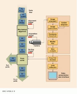
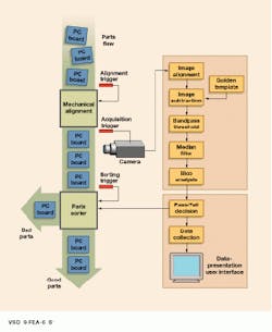
In a typical PC-based circuit-board inspection system, a CCD camera examines one board every two seconds, looking for defects and making a pass/fail decision. First, the system aligns the board image to a reference template. To detect defects, the system subtracts the two images, thresholds and filters the result, and performs a analysis on the structures or blobs in the image. The system makes a pass/fail decision based on defect size and location.
Several mechanical aides were needed to reduce the PC`s processing requirements. One was proper lighting. Even though the objects under inspection were planar, careful lighting avoided specular reflections that could erroneously register as defects. The other mechanical aide was a fixture that aligned the circuit board to the stored image within a few millimeters. Without the fixture, the software would have to translate and rotate the board image before performing the image subtraction. The extra processing would have lowered the system`s throughput to the point where it was unusable.
PC-based image systems can be used where inspection times are on the order of seconds. In this inspection system, PCBs are examined every two seconds. In coperation, the system aligns the board image to a reference image or template, subtracts the two images, thresholds and filters the result, and performs a blob analysis. A pass/fail decision is made based on defect sizes and locations.
Mid-range system checks cans for chips
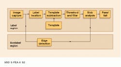
A container label- and defect-inspection system illustrates the capabilities of a mid-range system. The system requires 600 ms to examine a cylindrical container for scratches, chips, and proper label placement. Working with a 1700 ¥ 1700-pixel image, the algorithm first locates the label and segments the image into label- and nonlabel regions.
In the label region, the system then performs a two-image subtraction using a "golden template" as reference. Potential label defects are detected by thresholding the difference, applying a median-value filter, and performing blob analysis. In the nonlabel region, the system performs edge detection followed by blob analysis. Once potential defects are identified, the system makes a pass/fail decision based on defect size, type, and location.
Ideally, two-dimensional (2-D) correlation would have been used to find the label. But this operation had to be circumvented to reduce the processing load and meet the application`s 600-ms response requirement. Except for careful lighting that is needed to properly illuminate the cylinder and avoid specular reflections, avoiding 2-D correlation was the only compromise that had to be made to meet the application`s objectives using a single C80 board.
This container label- and defect-inspection system uses PCI-based PCs with attached processors. The Ariel C80-based Griffin PCI imaging system examines a cylindrical container for scratches, chips, and proper label placement in 600 ms. Once potential defects are identified, the system makes a pass/fail decision.
This container label- and defect-inspection system uses PCI-based PCs with attached processors. The Ariel C80-based Griffin PCI imaging system examines a cylindrical container for scratches, chips, and proper label placement in 600 ms. Once potential defects are identified, the system makes a pass/fail decision.
VME systems target web inspection
Because of its high system bus bandwidth, reliability, and extensibility, the VMEbus is often used for high-end imaging systems. At Ross Microsystems (Nanuet, NY), VME boards from Datacube (Danvers, MA) were used to develop a web-inspection system for patterned metal. The system, which examines a 1-m-wide sheet of patterned metal moving continuously at 10 m/min, must provide 100% coverage while looking for defects as small as 50 µm (see figure).
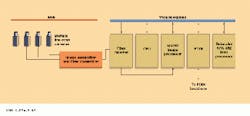
The system uses multiple line-scan cameras with 30,000-pixel resolution and 7500-line/s scan rates to acquire web data. The acquired data are transmitted via a proprietary 30-Mbyte/s fiberoptic link to the VMEbus-based Swath Processing Nodes (SPNs), which may be located up to 1000 ft away from the web area.
The system provides up to 18 SPNs, each of which analyzes a single swath of the web. Each VMEbus-based SPN contains a Datacube MV250 image processor, a Datacube APA512+ hardware blob-processing board, and a pair of Motorola CPU boards (PowerPC or 68040 based), which serve as a control computer and master results processor. Communications between the VMEbus systems and the rest of the factory are implemented via a 100-Mbit/s FDDI link.
Swath Processing Nodes automatically detect when metal is in position for inspection and then collect and analyze image information. The image-processing sequence begins with pattern-removal, followed by thresholding and a median-value filter. After performing blob analysis, the system makes a pass/fail decision based on defect size, type, and location.
Because of its high system bandwidth, the VMEbus is often used for high-end imaging systems. In this web-inspection system, VME boards are used to process images of a 1-m-wide sheet of metal moving at 10 m/min.


