Medical x-rays and digital radiology advance image diagnostics
Medical x-rays and digital radiology advance image diagnostics
Digital imagery is eliminating the cost and inconvenience of processing x-ray film-based images.
By John Haystead, Contributing Editor
High-resolution digital imagery is expected soon to replace conventional x-ray film and chemicals in clinical radiology. In addition to providing physicians with improved access to medical images and increased diagnostic information, digital imagery will also eliminate the cost and inconvenience of processing, storing, and transporting x-ray-film-based images.
According to Jeff Irish, general manager, global x-ray, at GE Medical Systems (Milwaukee, WI), film-based images now account for approximately 70% of all clinical images. When combined with sophisticated postprocessing and analysis software, the new digital x-ray technology promises major ad vance ments in computer-aided detection and diagnosis.
The GE digital radiography system is based on the company`s amorphous silicon/cesium iodide (CsI) digital detector technology (see "Digital detector technology," p. 32). Similar to flat-panel-display technology, the amorphous silicon system is a single-piece, flat-panel-detector design that eliminates potential misregistration or stitching artifacts. As described by Frederick Pla, marketing manager for GE`s digital detector technology, the detector is "basically one large integrated circuit laid out on a 50 ¥ 50-cm glass substrate." The detector itself is about 41 ¥ 41 cm.
The CsI-based detector can potentially capture more than 80% of the original image information, compared to less than 40% for other image-intensifier/CCD-digitization systems. In October 1998, GE received US Food and Drug Administration (FDA) clearance to market a system based on its detector technology for chest examinations and will be delivering a product for clinical use later this year. Eventually, the detector will be incorporated through out the company`s x-ray-system product line. Among several ongoing development activities, GE has a partnership agreement with the University of Chicago Hospital (UCH; Chicago, IL) to apply the technology to mammography.
Computer-aided diagnosis
The UCH is using the GE full-field-digital-mammography (FFDM) system as part of its research into a computer-aided-diagnosis platform to help radiologists identify and interpret mammograms. Breast cancer is the leading cause of death among women ages 35 to 54, and, by the end of the decade, approximately 1.8 million women are expected to be diagnosed with invasive breast cancer.
Several studies have shown that approximately half of the undetected cancers are missed due to observational oversights by radiologists. The hospital`s goal is to provide a system that will alert radiologists to look closer at specific areas of an image. The project has been underway for more than ten years with support from the National Cancer Institute, the American Cancer Society, the US Army, and the Whitaker Foundation.
University of Chicago Hospital is developing diagnosis algorithms that will assist radiologists and physicians in identifying breast lesions and, once identified, in deciding if a biopsy is warranted (see Fig. 1). The hospital already has an initial clinical system in place that uses digital imagery captured from x-ray film. As pointed out by Robert Nishikawa, medical physicist and assistant professor in the University of Chicago radiology department, the hybrid system has improved the lesion-identification process, but there are still problems with the approach. "Not only is the initial film quality suboptimal compared to direct digital acquisition, but the interim digitization step further degrades the image quality."
There are also operational issues associated with the process, because someone must conduct the digitization process. "This is not a trivial task in a busy hospital," notes Nishikawa, "and it also causes delays in delivering the film to the radiologist as well as in getting data to our algorithms."
A principal objective of the UCH diagnosis-system design is to make the user interface as transparent and easy to use as possible for the radiologist, which, says Nishikawa, "makes reducing the amount of excess movement that the radiologist must make a major criterion. Just turning your head from side to side is bothersome." Radiologists typically read mammograms on a lightbox, and the current UCH system provides a collocated CRT monitor on which possible tumors are highlighted with arrows. The radiologist must therefore look back and forth to correlate the film and monitor images.
Real-time, high-quality digitization is projected to transition this process toward total soft-copy analysis, whereby the radiologist can switch back and forth from diagnosis-assisted to raw imagery. The hospital has been working on this process with a 1600 ¥ 1200-pixel color CRT monitor and a touchscreen interface.
Because a mammogram screening involves taking two images of each breast at different angles, it is desirable to display the four images simultaneously. The UCH system displays reduced-size versions of the mammograms in a line across the top of the monitor with colored arrows to indicate the two types of lesions radiologists are looking for: calcifications (which show as small bright areas) and masses (which show as larger, more circular regions). Colored arrows highlight both types of lesions. Although radiologists can usually identify masses easily, calcifications are often 0.5 mm or smaller in diameter and are difficult to detect. By touching the monitor screen, the radiologist can zoom up on these areas.
The UCH has been working with the FDDM system since August 1998, but Nishikawa says it will still be another few years before a clinical diagnosis system based on digital technology will be commercially available. Among the tasks ahead, enough data must be collected from the system to "retrain the diagnostic algorithms." Adds Nishikawa, "Although we can probably use the same basic code, we`ll have to tune it differently, which will be the hard part." Although UCH is a member of the International Digital Mammography Development Group and receives image data from most group centers with digital equipment in place, Nishikawa says the process is still slow. "Because images are collected under research as opposed to clinical protocols, only a few images are received per day per site."
The UCH CAD system is being developed with a variety of software languages, including Fortran, C, and C++. The software was initially developed for a Sun Microsystems (Mountain View, CA) RISC 6000 machine but is now also being migrated to O2 and UltraSPARC platforms. Program size is currently about 10,000 lines of code. R2 Technology (Los Altos, CA) has also licensed many UCH patents for its FDA-approved "Image Checker" product.
Approved system
R2 Technology`s ImageChecker M1000 computer-aided-detection system identifies and highlights "regions of interest" (ROIs), such as microcalcifications and masses, for radiologists following their routine interpretation of a mammogram (see Fig. 2). The marked ROIs are associated with a visually perceptible structure that has some of the generally accepted geometric characteristics of microcalcifications or masses. The marked areas might be something other than an actual abnormality, however, but these areas are recognized as such by radiologists upon review of the original mammogram. The system uses two different markers to identify ROIs: a triangle for a cluster of bright spots, corresponding to a microcalcification, and an asterisk for a density with radiating lines, corresponding to a mass (see Fig. 3)
Films are scanned using a 50-µm laser film digitizer into 12-bit digital images and then identified by a barcode reader. Once digitized, the images are processed via neural-network algorithms performing approximately 1 billion operations per film. Scan-to-display time runs approximately four minutes for a typical four-film case.
The system ranks its findings according to preprogrammed thresholds. By design, only low-resolution images are produced on the monitor to preclude its use as a diagnostic tool. Only original mammograms can be used for interpretation by radiologists (see Fig. 4).
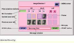
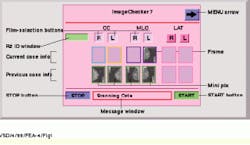
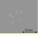
Figure 1. Expanded view of R2 Technology`s ImageChecker touch-sensitive display screen shows that up to one-half of early breast cancers contain little clusters of microcalsifications, tiny deposits of calcium, that look like a constellation of faint stars on a mammogram. The University of Chicago Hospital is developing a computer-aided-detection program that will recognize these "stars" and help alert the radiologist to their presence.
Figure 2. R2 Technology`s ImageChecker M1000 System searches an image for clusters of bright spots, suggestive of microcalcification clusters. When features in the mammogram meet the generally accepted criteria for microcalcifications, the ImageChecker places a triangular marker over the centroid of that region on low-resolution display images.
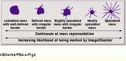
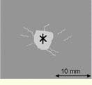
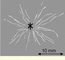
Figure 3. The ImageChecker M1000 System image-processing software searches for patterns of dense regions with radiating lines, suggestive of masses or architectural distortions in the mammogram. The system uses an asterisk to mark patterns associated with masses. The marker is positioned on the low-resolution display images at the point of maximum convergence of the radiating lines. Masses can be thought of as occupying a continuum ranging from well defined to highly spiculated. The less-pronounced radiating lines are not marked because of the absence of a central mass (left). Some of the less-pronounced radiating lines are marked because of a central mass (middle). The pronounced radiating lines are marked regardless of the absence of a central mass (right).
Figure 4. Radiologist reviews mammograms mounted on a motorized viewer equipped with display monitors. The system uses two different markers to identify the regions of interest: a triangle for a cluster of bright spots, corresponding to a microcalcification, and an asterisk for a density with radiating lines, corresponding to a mass. These mass characteristics provide a relative likelihood that they will be marked by the ImageChecker.
Digital detector technology
A key benefit of amorphous silicon is that it exhibits a high detective quantum efficiency (DQE)--a measure of medical image quality representing the combined effects of detector noise, contrast performance, signal-to-noise ratio, and spatial frequency. The amorphous silicon detector delivers a higher DQE than x-ray film, computed radiography, and current flat-panel selenium-based digital imaging systems, especially at the low-to-mid spatial frequencies where most clinically relevant information resides. As a result, it can potentially capture more than twice the original image information than fluoroscopy systems and other image-intensifier/CCD-digitization systems.
Digitization of the x-ray signals takes place within the detector itself. A cesium iodide (CsI) scintillator absorbs the x-ray photons and converts them to light. Because of its high reliability and excellent x-ray aborption characteristics (about three times that of selenium), CsI produces high-quality images at lower x-ray doses. A thin layer of CsI material is configured into approximately 10-µm-diameter "needle-like" structures on top of the amorphous silicon panel to minimize scatter and blurring. As described by Frederick Pla, marketing manager for the GE digital detector technology, the structures basically trap individual x-ray photons and conduct the light energy to the detector array similar to the activity of a fiberoptic filament.
A low-noise amorphous-silicon photodiode/transistor array then absorbs the light and converts it into an electric charge proportional to the detected x-ray energy. This array contains 4 million photodiodes (2048 ¥ 2048), each representing a pixel in the image matrix. Low-noise analog-to-digital (A/D) electronics rapidly scans each column of the array to read out the charge at each pixel.
Says Pla, "A challenging task for x-ray imaging is producing high-quality imagery while minimizing x-ray exposure to the patient, particularly for long-duration, real-time imaging procedures." To do this, the noise of the detection electronics must be comparable to the energy of a single x-ray photon at each pixel.
GE is now implementing the fourth generation of custom-designed ASIC A/D electronics for the panel. The panel contains two types of custom ASICs--one handles the column-by-column scanning and the other handles the pixel readout and A/D conversion. To maximize readout speed for real-time imaging applications and minimize noise, the developers chose not to multiplex the signals but instead to provide a dedicated A/D converter for each column of the array. As a result, each of the panel`s eight readout ASICs contain 256 14-bit A/D converters to handle the conversion process for the entire array.
Better than film
An additional benefit of the detector`s sensitivity and matrix size is wider latitude, or film or detector response as a function of x-ray exposure. X-ray film, for example, has a narrow exposure range for usable imagery requiring precise x-ray intensity and tube-voltage parameters. In fact, says Pla, "about 10% of all film x-rays have to be redone because the film was either under- or overexposed."
The greater sensitivity of the amorphous silicon detector allows it to obtain usable images over a much wider range of exposure conditions. In addition, the tube voltages used in many existing x-ray systems are optimized for the relatively long exposure times required by film, whereas with the more-sensitive digital detector, "it may be possible to use higher-kilovolt tubes for better penetration without increasing the total radiation exposure to the patient."
Because the overall system requirement is to provide image sizes comparable to those of x-ray film, pixel pitch size is also directly related to the application. The larger the pixel size, the more photons will be captured and the greater the resolution. A chest x-ray, for example, does not require as high a resolution as mammography. Currently, the chest x-ray radiography panel`s pixel pitch is about 200 µm, while for the mammography system, the pixel pitch is currently on the order of 100 µm.
Gray shades
After A/D conversion, the signal is passed to the x-ray system`s proprietary image-processing system, which contains a combination of custom and off-the-shelf digital-signal-processing components. Further local processing can be done at the radiographic acquisition workstation or remotely.
The wide dynamic range provided by the detector`s 14-bit A/D conversion captures thousands of shades of gray for system analysis, which can be applied to equally detailed pathology databases. To capture as much of this usable medical information as possible while also providing clinically useful information to radiologists, however, the data must be preprocessed down to levels distinguishable by the human eye. Processing level, transform, and filtering information vary according to the anatomy being examined, and each system has to be configured differently to provide and enhance the features of interest to the particular application.
