Vision system inspects disposable slides
Multiple inspection stations monitor automated blood-analysis slide-production line.
By C. G. Masi, Contributing Editor
Automated blood-analyzer instruments quantitatively measure levels of more than 40 clinically significant compounds found in blood samples and do it rapidly, inexpensively, and reliably using a disposable slide. To make the slide-production process profitable, a medical-device manufacturer needed to use as much automation in the production line as possible. Several inspection points were needed in the line to keep production quality high because the slides are used in a clinical setting and thus no defects could be tolerated.
To meet these goals, process engineers working on the project decided to combine 100% inspection with statistical process control (SPC), which allows them to monitor process variations and correct any unfavorable trends before they reach unacceptable levels. Using machine vision to collect the quality control data made it possible to automate the entire process-control loop with real-time feedback.
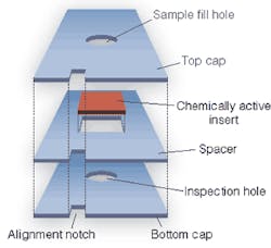
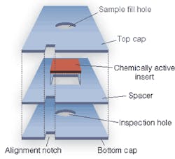
Each slide consists of a sandwich of three plastic layers enclosing a chemically active insert (see Fig. 1). The insert is a porous plastic wafer carrying a reagent that changes color when it reacts with a particular target compound. The analyzer delivers a specific slide to the metering station. Since each slide type quantifies the concentration of one compound, the number of slides required equals the number of target compounds in the test protocol.
The slide’s first stop within the analyzer is a metering station, which delivers a specific volume of the blood-serum sample through an opening on the top of the slide. The sample wets the chemically treated insert, starting a chemical reaction that changes the insert’s color according to the target compound’s concentration in the sample. The slide then moves to the incubation and read areas, and the next slide to be read moves to the metering station.
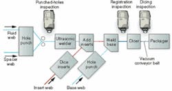
In the manufacturing process, the material comes in by way of four webs: clear styrene tapes approximately 25 × 1 mm thick for the fluid, spacer, and base layers, and a narrower tape of chemically treated porous plastic for the inserts (see Fig. 2). The first step is to simultaneously punch a circular fill hole in the fluid web, a square hole in the spacer web, and square registration notches in both to help align the components. The first inspection step verifies that the punched holes are in the right place compared to the registration notches, and properly centered in the webs. Then, they go to an ultrasonic welding station that forms a fluid-tight seal between these two webs.
FIGURE 2. Production of blood-analyzer slides is a web process. Four webs (fluid layer, spacer layer, reactive insert, and base layer) come together to form the complete slide. To ensure the very highest quality while maintaining high production volume and low cost, the production line includes three inspection stations networked to form a closed-loop control system. The three inspections occur at three critical process points. The first checks registration of punched holes in the fluid and spacer layers. The second ensures that the chemically active inserts and bottom layers go together properly. The third makes sure that the dicer cuts the web in the correct spots so that the holes will all line up properly when the slides are inserted into the analyzer.
Inserts are added, but before they can be positioned they have to be trimmed to fit into the square cavity formed by each spacer-web hole. As the inserts go into position, the base layer (with its holes and registration notches punched, as well) gets welded to the sandwich.
This is the last point at which the material is in web form, so it is important to do a final inspection to make sure the components have maintained alignment and, especially, that the base-registration notches line up with the registration notches on the fluid and spacer webs. The next station in line-the chopper-cuts the web into small pieces that have to be individually controlled. The engineers use a vacuum belt that is approximately one-third the slides’ width to carry them from the chopper to the packager.
Since the post-dicing inspection system cannot see the center portions of the slides, it has to use the registration notches to make sure that the chopper made cuts in the right places. If the chopper gets out of registration, the fill and inspection holes will not line up properly in the analyzer, affecting the clinical test performance. So this third inspection station measures both the distance between the cuts (that is, the length of the slide in the web-movement direction) and the notch’s position with respect to those cuts.
The final process step is to package the slides in packs of 18, 50, or 60 slides per package. A final inspection checks both the quality and content of the package label. For example, the inspection system makes sure the label information correctly identifies the target compound for the slides in that package. It also makes sure the barcode is clear and correctly positioned to allow the barcode reader built into the analyzer to identify the slides.
Inspection Hardware
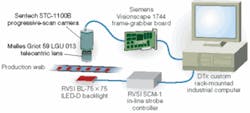
Turnkey-system integrator Zynergy Solutions developed the automated inspection stations. The first three inspection systems are virtually identical. The systems use backlighting from a strobed BL-75 × 75, I LED-D backlight manufactured by Siemens Energy and Automation Nerlite Division to obtain a sharp silhouette image through a Melles Griot 59 LGU 013 telecentric lens mounted on a Sentech STC-1100B double-speed progressive-scan camera.
“We’re using infrared [backlighting] because the chemistries are somewhat light-sensitive,” says David Sprankle, the Zynergy Solutions applications engineer who designed the system. “If we expose the slide under inspection to white light, it does affect the chemistry. Infrared does not-at least during the time we’re doing the test.”
To prevent motion blurring, Sprankle added an SCM-1 in-line strobe controller (also manufactured by Siemens) to hold the exposure time to 50 µs. Strobing the LED backlight also minimizes photobleaching of the slides’ inserts.
The camera’s double-speed capability allows Sprankle to get a full 640 × 480-pixel resolution image out every 20 ms. Since the system operates in the IR (the backlight’s output centers at 900 μm), he chose a black-and-white camera. The camera puts out an NTSC standard analog signal into a Siemens Visionscape 1744 frame-grabber board plugged into the host computer.
Sprankle says that using a telecentric lens is good vision-based-measurement practice. Telecentric lenses hold system magnification constant, regardless of working distance, so there is no danger of measurement errors arising from movement of the camera or web.
The host computer is a rack-mounted industrial computer built to Zynergy specifications by DTx. The unit carries three frame grabbers acquiring images from the first three inspection systems.
FIGURE 3. The inspection stations are virtually identical, using infrared backlights to highlight the significant features. Infrared avoids photochemically damaging the active ingredients in the inserts. A telecentric lens ensures that the measurements are robust against small relative movements of the camera and web. The CCD camera acquires the image and sends it in analog (NTSC) format to a frame grabber board in the host computer. Strobing the backlight freezes the web’s motion during image acquisition.
One of the most useful features for maintaining process health is displaying images as a live video. The system monitor can display each frame as the camera produces it, at 60 frames/s. “You can see it moving back and forth a little bit, even while the technicians adjust the machine,” Sprankle reports. “They can tell how well the machine is running by just viewing the image.”
The computer’s primary job is to analyze the images from all three inspection stations and quantify deviations from nominal values, such as positions of drop holes from the edge of the web, for both 100% inspection and SPC purposes. Both require quantitative measurements of all the critical dimensions for each slide calculated in real time.
For 100% inspection, software compares each critical dimension to the appropriate inspection criterion and decides whether to accept or reject the part. Since it is a web process, however, the system can’t just pull a bad part out of the stream. For example, a part (or a series of parts) with the drop hole off center will be flagged by the first inspection station. The computer has to retain that information until the web has been diced. It passes the identifying numbers of the parts to reject to the packager, which has the ability to shunt them off to a reject bin as it handles the slides separately.
SPC software compares the stream of critical dimension measurements to the appropriate control limits and looks for trends that may indicate that the process is drifting out of tolerance. By monitoring such trends, the software can give early warning of impending difficulties, allowing technicians to adjust the process equipment on-the-fly without shutting down the webs. If this real-time SPC system works as it should, the process never needs an unplanned shutdown, and virtually no parts need ever be rejected. This belt-and-suspenders quality approach makes it virtually impossible for a less-than-optimal slide to get through.
Features, advantages, benefits
“We work in the medical-device field, and meeting governmental regulatory requirements is of utmost importance,” says Gerald Meiler, engineeering manager at a medical-device manufacturer. “The challenge from an operations standpoint is to improve quality without impacting yield rates. Adding inspection never results in less waste, it only results in more waste.
“Closed-loop systems, on the other hand, generally increase productivity. The ability to send discrete signals for product tracking and measurements at a speed fast enough to make on-the-fly corrections made it possible to enhance productivity with minimal impact on the product stream. Yields are typically more than 99.8%.”
Company Info
DTx
Melbourne, FL, USA
www.dtx.com
Melles Griot
Rochester, NY, USA
www.mellesgriot.com
Sentech
Carrollton, TX, USA
www.sentechamerica.com
Siemens Energy and Automation
Alpharetta, GA, USA
automation.usa.siemens.com
Siemens Energy and Automation Nerlite Division
Weare, NH, USA
www.nerlite.com
Zynergy Solutions
Rochester, N.Y, USA
www.zynsolutions.com


