Marking/vision systems inspect PCBs
Combining a laser marking system and barcode-verification system speeds the production of electronic components.
By Andrew Wilson, Editor
Founded in 1989 by Tim Pilson and Ed Metcalf, Conveyor Technologies is a designer, developer, and manufacturer of material-handling systems for electronic assembly and other in-line assembly applications. Offering products that range from single conveyors to custom-built material-handling systems, the company was initially started to take advantage of the new equipment required in the manufacture of surface-mount printed-circuit boards (PCBs).
“In the past,” says Jason Vann, sales manager and systems architect at Conveyor Technologies, “we could build a single conveyor system that would suit the needs of many manufacturers. Now, however, with increased complexity and shorter PCB runs, customers such as Fuji and Tyco are demanding systems that are built to order.”
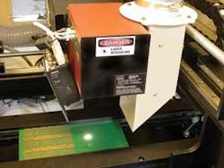
Says Vann, “We have noticed that while a number of companies were supplying lasers capable of barcode marking and barcode scanners that would image the board and verify the barcode placement, no manufacturer offered a PCB-handling system with these both of these functions.” Seeing this opening in the market, Vann and his colleagues set about designing a fully integrated conveyor system capable of performing these tasks (see Fig. 1).
null
BOARD POSITIONING
Laser marking of PCBs is a relatively new technology. Previously, labels with barcode numbers were placed on the PCBs and later verified by barcode readers. While this system was effective, any poor or defective label or label placement needed to be tracked through the system. Should such an event occur, the PCB would then have to be rejected, the label removed, and the board returned to the production line for label replacement.
“In addition,” says Vann, “since boards are designed differently, the operator must reset the label-placement system manually to ensure that the label is placed on free real estate on the board. Replacing label placement with barcode laser marking overcomes the problems of poor or defective label placement, while integrating a vision-based barcode reader allows the operator to rapidly reset the machine visually.
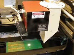
“The engineers needed to seamlessly integrate the flow of PCBs along the conveyor belt with an inspection station that integrated PCB stop placement, laser marking, machine vision, and barcode reading” (see Fig. 2). “As boards are loaded onto the front of the conveyor they are moved under the inspection station using a servomotor under control of a PLC from Omron.
“As the PCBs enter the inspection station, the edge of each board is detected by a convergent beam sensor, also from Omron, interfaced to the PLC that slows the motion of the conveyor belt,” says Vann. “These types of sensors are diffuse reflective sensors with a narrow beam width. Positioning the emitter beam perpendicular to the target and the receiver at an angle allows the receiver to focus on a small area of the board, ignoring objects in the background. This increases the sensor’s accuracy.”
Once the conveyor belt slows, the board travels under a similar sensor, which halts the position of the board in the inspection station. The sensor is attached to the PLC and triggers a pneumatic stop from SMC to stop the board precisely in the inspection station.
“Because each batch of boards can vary in thickness,” adds Vann, “and the laser marker and vision system are mounted at a fixed distance from their surface, the camera and laser-to-object distance will vary with each batch.” To overcome this problem, each board is raised to a specific fixed height in the text station using a pneumatically controlled test jig that is also controlled from the PLC. “In this way,” says Vann, “no matter what how thick the PCBs, they will always be precisely aligned for marking and barcode reading.”
MAKE A MARK
When the board is properly positioned, a Data Matrix code is marked on the PCB under control of the PLC using an FH “Index” Marking Head from Synrad that uses 7 W of laser power. “This laser energy is controlled so that only the surface layer of the PCB is affected. The mark does not penetrate this layer, leaving the continuity of the underlying copper intact,” Vann says.
After the board is marked, the Data Matrix code is verified using a Quadrus EZ barcode scanner from Microscan. Capable of up to 60 decodes per second, the scanner can read a number of different barcode topologies from Data Matrix, RSS, PDF417, and all linear barcode types. “By providing 17 different validation parameters, including symbol contrast, print growth, axial nonuniformity, and center shape/offset, the reliability of each barcode can be accurately measured,” says Vann. The data are then transferred to the system’s host PC over an Ethernet interface.
After each board is correctly marked and verified, the pneumatic stage releases the board, which is then moved along the conveyor, and the process repeated. Should the system detect a PCB that is badly or poorly marked, it can be removed from the production line before the board is populated.
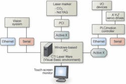
Developing the graphical user interface (GUI) for the system required seamlessly integrating motion control, laser marking, barcode reading, and PLC software from numerous vendors. “From the outset, we realized we could not develop all this software alone,” says Vann, “so we used Microsoft Visual Basic to integrate these disparate components using Active X controls.
“Running under Windows, the Omron CX-PLC Programmer software, for example allows logic programs to be easily created with an Explorer type interface. And because the software supports standard Microsoft COM/DCOM and Active X technologies, programs developed with the software could easily be integrated with the system’s GUI written in Visual Basic,” adds Vann.
Similarly, Synrad’s Windows-based laser markingsoftware, WinMark Pro, can be programmed to have a number of pull-down menus, dialog boxes, and toolbars. “This allows product-marking tasks and routines to be rapidly altered if necessary. As with Omron’s software, control marking can be accomplished from any ActiveX-compatible environment, including Visual C++ and Visual Basic. “The software also allows developers to import different file formats, mark directly from a PC or networked database, and set up automated processes such as serialization and batch coding,” says Vann.
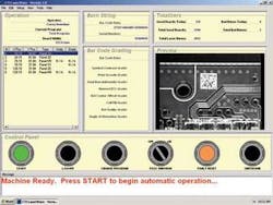
Verification data from the barcode reader are also imported into the GUI and displayed to the operator. In this way, the user interface both controls the machine and presents barcode data to the operator (see Fig. 3). From this interface, the operator can start and stop the machine, as well as quickly visualize the number of good and bad parts and their quality. The operator can also reset the machine and change the marking programs that need to be run.
“One of the unique features of the system,” says Vann, “is that it lets the operator preview the board by digitizing the RS-170 video output of the Quadrus E-Z scanner in a preview window of the GUI. While in previous systems locating free real estate on new batches of boards was a manual process, the operator can now use the video window to jog the board and set its position under the marker. Once set, the system stores the correct x-y data for where the board is to be marked, and batches of boards can be automatically marked and verified at that position.
Company Info
Conveyor Technologies
Sanford, NC, USA
www.conveyor-technologies.com
Microscan
Renton, WA, USA
www.microscan.com
Omron
Schaumburg, IL, USA
www.oeiweb.omron.com
SMC
Indianapolis, IN, USA
www.smcusa.com
Synrad
Mukilteo, WA, USA
www.synrad.com


