Automated inspection ensures electrosurgery needles meet exacting specifications.
By C. G. Masi, Contributing Editor
First used in the late 1960s, electrosurgery is a minimally invasive technique where radio-frequency (RF) electric current cuts or cauterizes tissue rapidly, reducing surgical trauma, bleeding, and healing time and preventing electrical stimulation of muscles in the current path. In its present form, electrosurgery uses RF current at a frequency between 100 and 500 kHz that is amplitude-modulated into a series of pulses with a duty cycle that can be changed to modify the rate at which heat is generated in the tissue at the incision site. High duty cycles provide high heat rates that vaporize cells near the needle tip, forming a cut. Low duty cycles (as low as 6%) provide much slower heating that cauterizes the tissue instead of vaporizing it.
Radio-frequency current flows from the RF generator to the electrosurgery needle tip held just over the incision site. It then jumps across the gap to the incision site as a spark. The current travels through the patient’s body to a patient return electrode, which provides a large-area patch through which current can exit the patient back into the external generator circuit.
Clearly, the technique uses currents high enough to cause damage. Preferably, that damage can be concentrated at the needle tip where it will do some good and minimized at the patient return electrode where it will not. The relative amount of damage depends on the relative areas of the two tissue-to-circuit contacts. Using a sharp needle tip and a wide patient return electrode concentrates the tissue damage at the incision and avoids electrode burns at the return site. The sharper the needle, the less current is needed to create the same surgical effect and the lower the potential for electrode burns.
Electrosurgery-needle manufacturer Point Technologies (a division of Angiotech) realized it needed to switch from manual inspection to automated inspection to meet customer quality expectations while achieving the required production volume. The company’s engineering department took on the task of creating the inspection station, which could then be used to inspect the company’s line of semiconductor-wafer test probe needles, as well. The engineers worked with vision consultant Jim Schott of Timberline Automation to create the vision system and integrate it with a mechanical system that Point Tech engineer Dave Senders built; a software system that was then programmed by engineering manager Steve Neely.
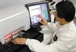
During inspection of electrosurgery needles, a technician clamps a fixture populated with needles onto a single-axis motorized stage under the inspection camera. The camera mounts on a gantry that moves it along a second horizontal axis and vertically to provide focusing. Once the operator keys in the required information identifying the lot and presses a start button, the host computer takes over motion control and image acquisition tasks. The system also provides a manual operation mode.
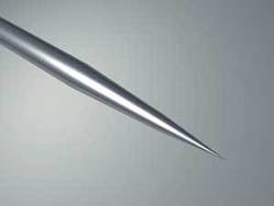
Point Technologies manufactures electrosurgery needles made of tungsten by a proprietary electrochemical etching process. Tungsten is a superior material for this application because it is 2.5 times harder than stainless steel and better able to withstand the heat involved in generating tissue-cutting sparks. Point Tech’s electrochemical etching process can produce sharper points on the tungsten needles than would be possible with a more conventional grinding process. What Point Tech needed was an automated inspection system able to rapidly measure needle-point dimensions at several places to ensure that the process was providing the correct taper.
The electrosurgery-needle inspection system includes two subsystems: a vision system and a motion-control system (see photo). The host computer coordinates activities in both subsystems and distills raw data into process information, which it uploads to an enterprise-level server. The server also carries test recipes for all the needle types the company produces. At the start of an inspection run, the host computer downloads the recipe to be run (based on operator input) on a lot of needles clamped into a fixture, then steps through inspections for each needle in the lot. If the lot passes, the computer prints out a tracking label. If the lot fails, the host signals the operator to send the fixture back to have the needles processed further (see Fig. 1).
A technician locks the whole fixture with its needles on a single-axis stage under the camera (see photo on p. x). The camera, in turn, is mounted on a gantry capable of moving it in two axes. The stage providesy-axis motion, while the gantry provides motion along x and z axes (z being the focus motion). The mechanical system was custom-built in Point Tech’s support shop
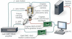
The host computer controls the three motion axes through a DMC-18 × 2 motion-controller board manufactured by Galil Motion Control. This board plugs into one PCI bus slot in a Dell Dimension desktop computer. The board drives the motion actuators through an AMP-19540 amplifier, also manufactured by Galil.
The host computer uses a test program downloaded from a server on Point Tech’s enterprise-level network. This program tells the motion control system where to focus the camera’s field of view to image each needle tip in turn (see Fig. 2).
Figure 2. A program downloaded from a server tells the motion-control system where to focus the camera’s field of view to image each needle tip in turn.
A Cognex CLM-LDLTP51X51 (2 × 2-in.) LED backlight silhouettes the needle under inspection for the camera-a Cognex CDC-200K monochrome CMOS camera with 1280 × 1024-pixel resolution looking through a Fujinon 114-0050 telecentric lens. The camera’s field of view is approximately 5 mm, which is enough to include the needle’s entire tapered portion, and the lens provides 1.8X magnification. The camera sends images to a Cognex MVS-8100D frame grabber installed in another of the host computer’s PCI bus slots.
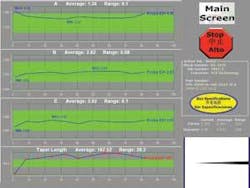
The computer uses Cognex VisionPro software for image acquisition and processing, and a custom supervisory program that Steve Neely wrote in Microsoft Visual Basic, which graphically displays data for a lot of needles (see Fig. 3). Measurements are taken at three positions back from the needle’s tip: 0.015, 0.025, and 0.050 in. (0.381, 0.635, and 1.27 mm). The third measurement is where the taper ends, that is, where the taper diameter becomes equal to that of the unetched needle body. Green shading shows the acceptable tolerance band.
Figure 3. Inspection system presents results for each lot in easy-to-interpret graphical form. The graphs superficially resemble statistical process control charts, with data overlaid onto green-shaded pass bands between upper and lower control limits. The main difference between these charts and conventional SPC charts is that, whereas SPC charts display trends over time, the needle inspection system’s charts display measurement data vs. position in the fixture.
When a lot passes, the system produces a report for the server’s archives and prints out a label that goes with the lot. That way, should any question arise about any needle, Point Tech can refer back to the original inspection results.
The system is capable of 100% inspection on a fixture of electrosurgery needles in 3 to 5 min., which is far faster than could be achieved by human inspectors using measuring microscopes. Measurement repeatability has proven to be within 20 µin. (±0.5 µm).
Features, advantages, benefits
“We particularly like the system’s versatility,” says Mike Bojanowski, manufacturing engineer at Point Technologies. “It allows us to easily change test parameters to reflect changing customer specifications. The touchscreen-based user interface makes it easy for operators to make these changes, and the system’s immediate readout of pass/fail results allows us to change manufacturing parameters in real time to maximize yield.
“As an engineer, I like the fact that I can get a real-time view into process parameters, such as manufacturing time and setup times. This really helps me to find ways to improve process flow and gain assurance that operators are consistently making high-quality parts. Most important, implementation of this vision system has dramatically improved customer satisfaction. Customers really like having a summary of test results for each shipment reported directly from our SQL server.”
null
