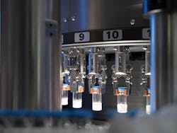
Vision system detects pharmaceutical contaminants
Sophisticated parts handling systems and innovative vision systems design team up to inspect a range of pharmaceutical products for foreign contaminants.
Foreign matter can jeopardize the product quality of pharmaceutical products that may include liquid suspensions, oily products, or powder. Since each product cannot be inspected in the same way, product-specific inspection machines must be developed that combine specialized combinations of mechanical transports coupled with novel vision systems that employ strobed LED lighting and high-speed cameras equipped with CMOS image sensors.
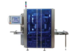
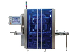
In developing such machine vision systems, Antares Vision (Brescia, Italy; www.antaresvision.com) has created a series of inspection machines that use this novel design to inspect a range of glass and plastic pharmaceutical containers of different sizes as well as the products contained within (Figure 1).
Figure 1: Antares Vision has developed a series of inspection machines that use this novel design to inspect a range of glass and plastic pharmaceutical containers of different sizes as well as the products contained within.
“The necessity for a product-specific inspection machine is due to the features of each product that cannot be inspected in the same manner,” says Alberto Reghenzi, Technical Manager with Antares Vision.
“To guarantee an accurate and consistent inspection of the part, how the cameras and lighting are positioned must be carefully evaluated. This will vary depending on whether the part needs to be rotated.”
He continued, “Such inspection systems must also be designed to accommodate the size of the vials or containers that need to be inspected and whether they are made of glass or plastic. All of these factors must be taken into account when developing such systems,” he says.
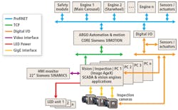
In creating the inspection system, Antares Vision engineers combined both the company’s machine vision and mechanical expertise into a system to perform this task (Figure 2).
Figure 2: The system consists of numerous cameras and LED units (only three are shown for illustrative purpose) that are interfaced to PC-based vision inspection engines. These, in turn, are interfaced over a TCP network to an automation and motion controller that is used to control the motion of the machine and the I/O rejection mechanisms.
In essence, the machine vision system consists of numerous industrial cameras and LED units (only three are shown for illustrative purpose) that are interfaced to PC-based vision inspection engines. These, in turn, are interfaced over a TCP network to an automation and motion controller that is used to control the motion of the machine and the I/O rejection mechanisms.
Inspection parameters
Specifically developed to inspect pharmaceutical preparations intended for injection purposes, the automated inspection machine is designed to detect and reject any units with foreign contaminant particulate and cosmetic and functional defects – such as cracks, scratches, or superficial dirt. Because a number of different vials must be inspected for the integrity of the vials themselves, any foreign particulate matter contained within, and whether the vials are correctly sealed; the Argo system that the company has developed can be configured in a number of different ways.
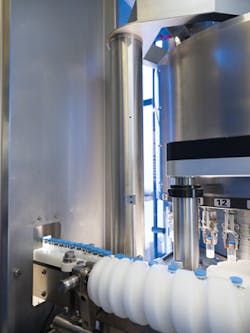
Figure 3: Vials of pharmaceutical products can be loaded either automatically or manually in batches into a feeder where they are singulated using split-screws.
In each inspection system, however, vials of pharmaceutical products can be loaded either automatically or manually in batches into a feeder where they are singulated using split-screws (Figure 3). These are then transferred to a series of starwheels into an inspection carousel. Here, a novel lifting mechanism uses single grippers to pick the parts from the starwheel (Figure 4). This mechanism serves a number of purposes.
“Because the inspection machine does not have a central column, i.e. parts are passed along a single conveyor - cameras can be placed at larger distances from the object, thus obtaining the perfect focus and a better depth of field without need for re-adjustment when a product change may occur,” says Reghenzi.
Figure 4: A novel lifting mechanism that uses single grippers to pick the parts from the starwheel where cameras mounted on a “boomerang mechanism are used to image the vials at different angles.
“Furthermore,” he added, “the LED lighting source can be placed on different sides around the product to be inspected (rather than just on one side) and the cameras can be angled (rather than point straight at the product).”
Better still, should the vials to be inspected contain a liquid, they can be easily spun, creating a vortex to better visualize any foreign matter that may be within.
Spinning liquids
To accomplish this inspection, only liquid substances need to be spun. Foreign matter that may be present in powdered substances is only visualized at the periphery of each vial since the use of X-rays cannot be used with such pharmaceutical products. To inspect both liquid and powdered substances, several different images are taken at different angles to accomplish this, as both the camera and lighting systems are mounted on a novel “boomerang” arm that moves around each of the vials as they are indexed through the inspection station.
Images are then transferred over the GigE interface to a PC-based vision inspection station for analysis. Instead of using an off-the-shelf machine vision software package to perform the inspection tasks, all the imaging algorithms were developed by Antares Vision, allowing the company to fully customize the inspection system while avoiding license fees.
For the liquid preparation, the container is spun to create a vortex in the solution which will make any free-moving particles float. This container is then illuminated with a white backlight from CCS America (Burlington, MA, USA; www.ccsamerica.com) and captured by a color GigE machine vision camera. Depending on customer requirements, these industrial cameras are supplied by companies such as Teledyne DALSA (Waterloo, ON, Canada;www.teledynedalsa.com) or Baumer (Frauenfeld, Switzerland; www.baumer.com).
Once illuminated by the LED lighting source, any foreign particles that are in the vial will become visible and can be detected in a sequence of images. Once the series of images has been captured, image subtraction is performed on the vision inspection-based PC from Imago Technologies (Friedberg, Germany; www.imago-technologies.com) and a blob analysis function is used to detect whether any foreign particle is present.
For non-liquid preparations, spinning is not necessary, as the container is simply rotated 360° in front of the camera, and the appropriate illumination is used to enhance any defects that may be present.
Here, captured images are once again transferred to a vision inspection-based PC and compared with a “golden standard,” which is considered as a benchmark and any deviations from this benchmark are then considered defective units.
Color checks
As the vials are rotated around the carousel and inspected for both foreign particles and defects, they are indexed to a third inspection station where an image of the bottom of the vial is captured.
At this stage, a color image of the bottom of the vial is imaged with a GigE machine vision camera. RGB images captured by the camera are then transferred to a PC-based vision inspection station. To correctly compare whether the color in the vial matches a “golden standard” reference, RGB images are converted to either LUV or CIELAB color space.
Since CIELAB was designed to be perceptually uniform with respect to the color vision of human beings, the same amount of numerical change in these values corresponds to about the same amount of visually perceived change.
By comparing these values, the inspection system can then determine whether the powder within the vial matches the correct standard. Furthermore, the system is able to determine whether the powder is uniformly distributed across the bottom of the vial.
After this inspection task is complete, the vials are lowered back onto an output starwheel. As these products are indexed around the starwheel, another camera system is then deployed to check whether the cover of the vial is correctly placed is defective and whether it is of the correct color.
As the products move though this inspection station, the results of the machine vision inspection tasks are transferred over a TCP/IP network to a SIMOTION, PLC-based motion control system from Siemens (Munich, Germany; www.siemens.com). The vials are then transferred to another starwheel where vials that have passed inspection must be sorted from any that have been determined to be defective.
To accomplish this, the SIMOTION motion control system accumulates the results from all the visual inspection stations and determines which parts can be accepted and which need to be rejected.
As the parts move around the final output starwheel, the SIMOTION controller then actuates a pneumatic rejection mechanism that sorts the parts into good and rejected batches. Vials that are determinted to be good are then boxed and batched by the manufacturer, while bad parts can be returned to the production line for reworking.
To guide the operator in both setting up the system and monitoring the production process, Antares Vision has developed a set of machine vision inspection graphical user interfaces (GUI) that are based on a common template, making the inspection software intuitive, while allowing the operator to visualize the production process.
These GUIs were developed in C# using Microsoft’s (Redmond, WA, USA; www.microsoft.com) Visual Studio. To do so, the software employs a recipe creation wizard page such that different parameters can be visualized as required. This also allows fine tuning of the system’s parameters should this be required and a production page that allows the system to be monitored during operation.
Using these graphical user interfaces, users are guided with graphical feedback, which allows them to intuitively locate the correct setting, parameters and image display, according to Antares Vision.
To date, Antares Vision has supplied nine of the world’s top twenty pharmaceutical companies with more than 25,000 such machine vision inspection systems, as well as 2,000 serialization lines to track the supply chain of such products as they are produced.
Companies mentioned
Antares Vision
Brescia, Italy
Imago Technologies
Friedberg, Germany
Baumer
Frauenfeld, Switzerland
CCS America
Burlington, MA, USA
Microsoft
Redmond, WA, USA
www.microsoft.com
Teledyne DALSA
Waterloo, ON, Canada
Siemens
Munich, Germany
About the Author

Andy Wilson
Founding Editor
Founding editor of Vision Systems Design. Industry authority and author of thousands of technical articles on image processing, machine vision, and computer science.
B.Sc., Warwick University
Tel: 603-891-9115
Fax: 603-891-9297
