Bosch Launches Vision System to Read Codes on Injector Nozzles
Bosch Group built and launched a machine vision system in 2023 at its plant in Curitiba, Brazil, to verify serial codes engraved on injector nozzles used in diesel engines. It replaced a smart-camera based system.
The injector nozzles, which Bosch (Gerlingen, Germany) sells worldwide, are a common part involved in moving diesel fuel into an engine’s combustion chamber.
The production process is highly automated at Bosch. At the start of the manufacturing process for the nozzles, an operator selects the specific parts to be produced and feeds the components into the automated manufacturing system. The system then produces and packages the nozzles.
This includes engraving serial numbers on the nozzles. However, capturing readable images of small, laser-engraved characters on a cylindrical surface can be difficult. And, depending on the metal, the contrast between the characters and the metal surrounding them can be minimal, compounding the challenges in capturing and reading numeric information.
The old optical character recognition (OCR) and optical character verification (OCV) system at Bosch was not up to the task. It produced too many false rejects. So, Bosch hired LumiVision (Pinhais, Paraná, Brazil), a systems integrator, to improve these results with a new vision system.
“The rejection rate of the old system was very unstable, ranging between 3% to 10%, depending on the product being produced,” says Adriano Hebling, technical director at LumiVision.
Improving Image Quality and Capture Speed
After analyzing the existing character-reading and verification process, LumiVision’s team concluded that the old system was not fast enough to keep up with a production rate of 7,000 parts per day. In addition, the smart camera’s images were not of high enough resolution to facilitate reliable code reading.
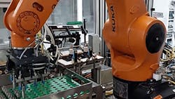
The old vision system was positioned at a station in which an industrial robot arm from KUKA (Augsburg, Germany) picked up two nozzles at a time from a tray and placed them on a rotating platform with cameras and lights positioned to capture images of the metal nozzles as they rotated on the platform. The robot then pivoted and dropped the nozzles into cylindrical white plastic shipping tubes.
LumiVision did not change this basic process or the robot, which is programmed to repeat the same movements continuously. However, the engineers upgraded the platform’s mechanical system with better rotation control using servo motors. They also designed the new vision system and installed it.
The new vision system comprises three area-scan GigE M2020 Genie Nano cameras from Teledyne DALSA (Waterloo, Ontario, Canada) with 16 mm Fujinon lenses from Fujifilm (Tokyo, Japan).
Two of the three 3.2 MPixel cameras capture images of the numeric code on the nozzles. Since the robot picks up two nozzles at a time, each camera focuses on one nozzle.
After the robot places the nozzles inside the plastic shipping cylinders, the third camera captures images of a barcode label affixed to the outside the plastic container.
The team chose area scan cameras instead of line scan cameras to minimize costs and complexity, notes Jorge Chang Diaz, strategic account manager for Zebra Technologies (Lincolnshire, IL, USA). Line scan cameras, which capture information from a single line of pixels at a time, typically require encoders to trigger the camera’s operation, adding to application complexity. They also tend to be more expensive than area scan cameras.
In addition to cameras, proper lighting is important to minimize the impact of different metals as well as the surface treatments performed on the metals during manufacturing. “There is a lot of variation in contrast between the metal background and the engraving on it,” Hebling says. To accommodate these variations without constantly adjusting the setup, LumiVision’s engineers positioned lighting modules to maximize contrast.
Two lighting modules from LumiVision illuminate the subject for each camera: a Line-Light Slim with diffuse light and measurements of 90 x 20 mm, which is positioned to shine down on the platform, and a Back-Light Slim with measurements of 65 x 65 mm, which shines up from the bottom of the platform.
To develop the automated steps for processing images and recognizing and verifying numeric information, LumiVision used Aurora Design Assistant from Zebra Technologies, which is a flow chart-based development environment that allows developers to build common machine vision applications without coding.
Using Aurora Design Assistant, the engineers at LumiVision developed an unusual image processing technique to decipher the numeric data contained in images. Each camera takes a series of images of the numeric information on the nozzles and stitches the center stripe of the images together, creating a flattened unwrapped picture. This then allows the numeric information to be recognized and read by the Aurora Design Assistant’s String Reader module, which reads characters based on their features, such as angled or curved lines.
“Although the speed of 38 fps initially seemed insufficient, the camera allowed us to reduce the capture frame from 2064 x 1544 pixels to 2064 x 50 pixels per image at a very high speed. Using the Zebra system, we assembled the images side by side, sufficient to form an image of 2000 x 4400 pixels in 1.2 seconds,” Hebling says.
The old system captured an image in 2 seconds.
Results from the image capture, identification and verification process are then transmitted to a central PLC at the factory, which controls the entire production process.
The new vision system runs on an industrial PC with an Intel (Santa Clara, CA, USA) i7 core with a Concord PoE frame grabber from Zebra. A Zebra Indio I/O card running inside the PC provides direct interfacing over an Ethernet network with the cameras, robot controller, and the factory’s PLCs.
Zebra’s Aurora Design Assistant orchestrates the entire vision process—from image processing to code verification. “It's all on one computer, one PLC, with one set of software,” explains Diaz.
LumiVision’s engineers also designed a web-based user interface using Aurora Design Assistant. Using the interface, a single machinist can manage the entire vision system.
After designing the new machine vision system, installation took less than four weeks. “However, more time was needed after installation to produce all the necessary product families and for fine-tuning and ensuring system productivity,” Hebling explains.
Results with the new Machine Vision System
After implementing the new system, Bosch achieved its goal of lower rejection rates, improving from 3-10% to 0.5-3%, Hebling says.
Factory managers are already evaluating next steps for the system, such as adding two more cameras to identify surface defects on the injector nozzles. Says Moises Santana, a vision system designer at Bosch involved in the project, “We anticipate developing future projects using a similar vision system.”
About the Author
Linda Wilson
Editor in Chief
Linda Wilson joined the team at Vision Systems Design in 2022. She has more than 25 years of experience in B2B publishing and has written for numerous publications, including Modern Healthcare, InformationWeek, Computerworld, Health Data Management, and many others. Before joining VSD, she was the senior editor at Medical Laboratory Observer, a sister publication to VSD.


