Smart optics help place BGAs
A combination of clever optics and vision systems allows reliable repair of printed-cicuit boards.
By Lawrence H. Brown, Contributing Editor
As one of the largest markets for machine vision, today’s semiconductor industry demands highly precise and repeatable systems. In rework systems for printed-circuit boards (PCBs), ball-grid arrays (BGAs) need to be replaced accurately when a repair or a change becomes necessary. Designing such a system requires ingenuity. Unlike components with leads that attach from the sides, BGA pads are not visible from the top of the part, making it more difficult to replace them. To align the part to the board, vision alignment systems must provide a simultaneous view of both the circuit board pads and the BGA.
To address this need Stan Kench, vice president of Precision Manufacturing Tools, has designed a bench-top tool for the manual removal, alignment, and soldering of a BGA part to a PCB. To lower costs without sacrificing efficiency and accuracy, Kench’s system lets the operator align the video image of the part to the PCB and manually fine-tune the placement of the part. The company’s B-1A Rework System features off-the-shelf machine-vision components, anx-y positioning system, and an integrated motorized heater head that lets the operator remove a part from a PCB and attach a replacement.
“Before purchasing a B-1A machine, EMA Services, a provider of surface-mount PCB-assembly equipment, removed and reinstalled parts by aligning BGA pads using a silkscreen outline that matched the part to the board,” says George Bunder, vice president of EMA Services. “Flux was placed on the part, and a heating device was used for the soldering. Using the B-1A machine has improved the quality of repair both in removing parts and soldering new ones in place.”
Double vision
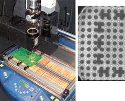
After a part has been removed, the new BGA must be aligned accurately with the board. Thus, the vision system needs to provide a simultaneous view of the BGA balls and the pads on the board (see Fig. 1). To illuminate both the part and the board, a custom-built halogen illuminator directs light through two LPA03M fiberoptic rings from Dolan-Jenner that are placed at the top and bottom of a Z03508AL beamsplitter from Esco Products. This beamsplitter is designed with a back mirror that faces the illuminator and halved diagonally at a 45º angle by a half-mirror coating. The fiberoptic rings illuminate the underside of the part and the pads on the board simultaneously. Images of both the part and the board reflect from their respective surfaces to the beamsplitter.
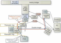
When reaching the diagonal of the beamsplitter, light from the bottom of the BGA passes through the half-mirror; the other half reflects to the back mirror, then again to the diagonal (see Fig. 2). The remaining light travels from the beamsplitter to a NT40-040 surface mirror from Edmund Industrial Optics, also angled at 45º, installed below an STC-630CT video camera from Sentech.
Figure 2.Sophisticated illumination and optical-beamsplitter techniques are used to capture a superimposed image with a digital camera, providing a simultaneous view of the BGA balls and the pads on the board.
When the image of the board reaches the diagonal of the beamsplitter, light passes through the half-mirror coating and deflects from the beamsplitter to the first surface mirror where it is refocused, with the image of the part, to the camera lens. With both images projected on the mirror and refocused to the camera lens, a simultaneous view of the underside of the part and the pads on the board is obtained.
Using a PXC200AF frame grabber from Cyberoptics, installed in a PC from Micros Northeast, the combined image is digitized and displayed on the PC. Lighting intensity for both top and bottom views can be adjusted manually on the front panel on the machine. Varying the intensity in both directions lets the operator contrast the superimposed image of the part with the board.
“We chose the camera for its low good light sensitivity and zoom properties,” says Kench. “However, if we are designing a system to image a 2-in.-square component, for example, then this may require a different lens and CCD camera.”
For large parts, such as column grid arrays, magnification of the images can be increased by installing a pan-and-tilt mirror. This allows the operator to zoom in on the superimposed image of the part and the board.
By viewing the simultaneous image on the monitor, adjustments are made manually to position thex and y axes of the positioning table where the board is located. The aligned image is then calibrated to the z axis. Alignment of the part to the board must be within 0.0005 in. As an added step, inspection using x-ray inspection techniques can be performed after positioning and soldering is completed.
Cautions and controls
Because a circuit board is a layered construction of materials, including plastic and copper, that is laminated, the heat necessary for soldering a part can cause warping, delamination, or both. To prevent damage, preheating the board is necessary. This is accomplished using infrared (IR) heating. “Many of our competitors use hot air for this task, but IR heat is more efficient transferring heat over distances,” says Kench.
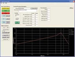
To control system functions, a PLC from WRD controls heating, optical illumination, and air control. Proprietary software monitors and controls theses processes from the desktop. Written in Visual Basic and running under the Windows XP operating system, the application monitors and records all the data used in the removal and soldering of the part (see Fig. 3). Solder and time profiles are displayed on the monitor with color-coded temperature-time plots. Software functions also include profiling, analysis to measure temperature vs. time curves used in the soldering process, and tools to measure ramp rates and time above temperature.
Figure 3. Proprietary software monitors and controls heating, optical illumination and air control from a desktop PC. Written in Visual Basic running under Windows XP operating system, the application monitors and records all the data used in the removal and soldering of the part.
null
X-ray inspection
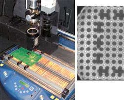
Mini Micro Stencil, a PCB repair and BGA rework service, uses the B-1A system to replace as many as 1000 parts per week. Because the company reworks parts as an outsource for electronics manufacturers, an added step of inspection is performed for each replaced part. “We use the Jewel Box 70-T x-ray inspection system from Glenbrook Technologies,” explains Adrian Nishimoto, a manager at Mini Micro Stencil. Using this system, solder-bond integrity and any misalignment or solder voids can be validated. Images can be magnified from 15 to 500 times with 100-line pairs/mm resolution. Mini Micro Stencil normally magnifies captured images by 15 times and finds errors in about 1% of its replacement work. The Jewel Box system is supplied with GTI-5000 BGA analysis and measurement software to image the soldered part.
Using this software, enlargements of each solder joint are displayed in succession while locating, measuring, and characterizing each joint automatically with user-defined pass/fail criteria. Any failures for a single or a series of ball joints are highlighted on the image with its characteristics.
As newer BGAs continue to increase in complexity, the ability to align the parts with PCBs is becoming harder. Vision systems such as the B-1A, and the systems that inspect their finished work, are becoming more important for PCB rework.
Company Info
Cyberoptics
Beaverton, OR, USA
www.imagenation.com
Dolan-Jenner
Lawrence, MA, USA
www.dolan-jenner.com
Edmunds Industrial Optics
Barrington, NJ, USA
www.edmundoptics.com
EMA Services
North Chelmsford, MA, USA
www.emaserv.com
Esco Products
Oak Ridge, NJ, USA
www.escoproducts.com
Glenbrook Technologies
Randolph, NJ, USA
www.glenbrook.com
Micros Northeast
Woburn, MA, USA
www.microsnortheast.com
Mini Micro Stencil
San Marcos, CA, USA
www.minimicrostencil.com
Precision Manufacturing Tools
Seabrook, NH, USA
www.pmtrework.com
Sentech
Carrollton, TX, USA
www.sentechamerica.com
WRD
Newburyport, MA, USA
www.wrdcorp.com


