Using telecentric lenses in inspection systems
By Spencer Luster
There are two myths regarding telecentric lenses: they have less distortion than conventional lenses; and they have greater image sharpness depth of field than conventional lenses. Neither of these statements is true. Both distortion (change in apparent magnification across the field of view) and image sharpness depth of field can be good or bad for any type of lens.
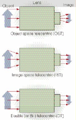
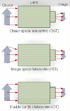
A telecentric lens is one that either receives mostly parallel rays of light from the object being inspected, images mostly parallel rays of light onto a camera detector, or does both (see Fig. 1). The first kind of lens is called object space telecentric (OST), the second is called image space telecentric (IST), and the third is called double (or bi-) telecentric (DT). There is almost no case in machine-vision applications where IST lenses are useful. Most commercial telecentric lenses are of the OST variety, with a few vendors (including Light Works) providing DT lenses.
Everyday experience teaches that conventional lenses (such as human eyes) see an object as being larger if it is close and smaller if it is far. This is part of how we judge distance by eye. But for gauging applications this property can introduce significant errors. Such cases occur on many types of conveyor lines, or where the distance to the part varies for other reasons. For example, bottles on conveyors can “walk” side to side between the rails, thus changing their distance to the camera that is viewing them. Components on circuit boards might be mounted at different heights with the camera looking down on them. The difference might seem small, but when trying to measure objects to within a few thousandth of an inch, the difference can be critical.
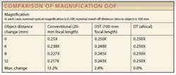
Good telecentric lenses overcome this problem. How far an object can change its distance and still appear to be the same size is called magnification depth of field. This is different from image sharpness depth of field, which is the commonly understood meaning of “depth of field.”
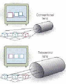
OST or DT lenses view the object field from the same or nearly the same angle across the whole field of view (see Fig. 2). This can be very important for gauging applications, especially for nonflat objects, or for applications in which you want to look down the bore of a tube or pipe to check for obstructions. You can think of them as being like a pair of calipers, providing true diameter or width measurements.
Any lens can be "stopped down," or have its so-called entrance-pupil diameter decreased. You make this hole inside the lens smaller by setting a higher f-number on the lens: f/22 is higher than f/16, for example, and so the internal hole is smaller. The cone of light rays from every object point that passes through the lens is narrower. When combined with the telecentric lens property of accepting rays of light that are mostly parallel, the lens can be very useful for detecting certain types of subtle defects in transparent or flat material. This feature of telecentric lenses is often overlooked.
One problem with telecentric lenses is that the lens itself must be larger in diameter than the object being inspected. This must be the case if the lens is only accepting rays of light that are nearly parallel. The larger the lens, the more expensive it is. Also, for many commercial telecentric lenses, especially OST lenses, it is difficult to provide good telecentric imaging with long working distance.
Applications
Large magnification depth of field means that telecentric lenses are ideal for a great variety of dimensional-gauging applications. Some typical gauging examples include threaded fasteners, machined parts, bottle geometry, and PCB component placement, or any time you want to measure something with little or no perspective error, or with varying distance.
Nongauging applications that make use of the constant-perspective property of telecentric lenses include inspection of tube or pipe bores and verification of hole clearance. An extreme case of this is a 4-in.-deep catalytic converter element captured with a very-large-field-of-view telecentric lens.
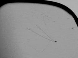
Keeping in mind that a telecentric lens’s purpose is to collect rays of light that are mostly parallel, one can use this property to detect defects that divert light away from parallel-for example, transparent material such as glass, especially when it is nominally flat. With sheet glass, polycarbonate optical disks, or plastic packaging, a variety of light-diverting or refracting defects can occur. These can be difficult to image with high contrast using conventional lenses and lighting. Telecentric lenses, however, can often make these subtle defects clear (see Fig. 3).
Lighting
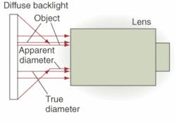
Even in backlit gauging, lighting can be a critical issue. Although the lens itself may accept only nearly parallel rays of light, the wrong light source used with the wrong object can send unwanted light rays “down the pipe” of the lens. A typical example is measuring the diameter of a cylinder or sphere, especially when the object is smooth and shiny (see Fig. 4). Light rays coming from well above and below the object can be reflected parallel to the lens. The true edges of the object are obscured by these bright reflections, making it appear to be a smaller diameter.
One solution is to mask off the diffuse light source so that it is only just larger than the object being inspected. An equivalent approach is to move the light source far behind the object. Either case reduces the angular range of the light rays that approach the object. Sometimes, however, this technique is impractical. The object may move around too much to allow effective masking, or there may be no room for a distant diffuse light source in the inspection station.
A more expensive, but technically superior, solution is to use a collimated backlight. Here, the illumination light rays start out nearly parallel. This provides a close source that still lets the object move about during inspection. Furthermore, this is a much more efficient use of light. When well aligned, all the rays of light from the collimator enter the telecentric lens and contribute to the image. Where a diffuse light source may require many watts of power to provide enough light for high-speed applications, a collimated source can operate at a tenth to a hundredth of the power.
