Near-IR camera sees wafer defects
Integrated near-infrared camera and microscope inspect bonded flip-chip devices for alignment and markings.
By Lawrence J. Curran,Contributing Editor
Capturing images through the bottom surface of silicon wafers can't be done with visible light. To overcome this limitation, a camera company, Indigo Systems (Santa Barbara, CA), has linked a near-infrared (NIR) microscope with a NIR camera to come up with a system for inspecting wafer irregularities in this manner. The company describes its apparatus as a complete imaging and analysis system.
The technique is especially suitable for viewing the alignment of two flip-chip or bumped wafers or chips that have been bonded together, as well as for "seeing through" ink, paint, and other opaque materials in a variety of marking applications. It also can be used to detect radiation in laser-based telecommunication, fiber-alignment and inspection, and optical-component-measurement and analysis applications.
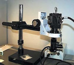
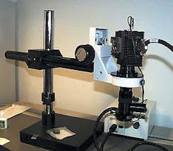
Indigo Systems has coupled its indium gallium arsenide (InGaAs) Alpha NIR camera with a Navitar (Rochester, NY) NIR zoom microscope lens in a system that also includes a National Instruments (NI; Austin, TX) data-acquisition board and NI LabVIEW virtual instrument software (see Fig. 1). Austin Richards, Indigo Systems senior applications engineer, points out that InGaAs detectors are highly resistant to damage from intense laser light, which allows direct illumination onto their focal planes for beam profiling.
Indigo Systems was approached by a prospective user who needed to inspect and capture images of the ends of miniature laser diodes during operation to determine if the diodes are functioning properly. To inspect a device that small, Richards says, the company looked for a zoom microscope lens with a field of view (FOV) that ranged from "a couple of inches down to less than a millimeter." It selected the Navitar Zoom 6000 lens that provides a FOV from 17 to 0.4 mm.
The smaller dimension is required to accommodate objects, devices, or phenomena as small as a few pixels wide (8-10 µm), such as the ends of laser diodes or tiny voids in silicon wafers. Another application for the vision system is to take images through the silicon to inspect circuitry on the bottom surface of bumped semiconductor devices after they have been bonded to a substrate.
System integrationThe principal hardware and software elements include the Indigo Systems Alpha NIR camera, which has a 320 X 256-pixel InGaAs focal-plane array. Richards points out that InGaAs detectors are especially sensitive to energy in the NIR and short-wavelength-infrared (SWIR) wavebands from 900 to 1700 nm. Exposure times for the camera can be set from 1 µm to 8 s. This wide, large dynamic range proves useful in measuring all aspects of a laser beam's profile—from its peak value to those at the outer fringes—without attenuating the laser signal.Richards says the ability to set long exposure times on the camera is a key advantage. "This feature is useful in detecting photoemissions from a source such as a transistor in an integrated circuit that emits a weak light signal when it malfunctions, making the malfunction easily detectable," he notes.
Indigo Systems has integrated the camera's sensor with an NI digital image-acquisition (IMAQ) board. The system has hardware and software in the form of an NI LabVIEW virtual instrument, which also includes a digital interface cable.
The virtual instrument allows bidirectional remote serial camera control, including exposure-time setting, invert/revert, gain state, and other functional parameters. It also enables users to acquire and display 12-bit digital image data, change sensor head settings, calibrate the sensor head, and analyze data using analysis tools such as regions of interest, line profiles, and spot meters.
Processing powerThe NI PCI-1422 series IMAQ board provides a serial interface and four RS-422 control lines for the camera. The board is installed into a Dell (Round Rock, TX) computer, captures as many as 16 bits of data at a clock speed of 40 MHz, and delivers a total acquisition rate of 80 Mbytes/s. The camera outputs pixel data at the modest rate of 4.8 Mbytes/s, however. An on-board 16-Mbyte memory accommodates on-board buffering, which captures large images and sustains real-time throughput.The IMAQ board in the vision system drives and receives data from the camera using the EIA-644 or low-voltage differential signaling protocol. This protocol is similar to RS-422, but works at lower voltage levels.
The Navitar Zoom 6000 lens is linked to the camera by a C-mount coupler. It is equipped with a 2X adapter from Nikon Instruments (Melville, NY) that doubles the lens power and effectively improves the FOV from about 2 in. to 1 mm, according to Richards.
However, he points out, if the Navitar 5X adapter is used and coupled with the 4.5X zoom range of the Zoom 6000 lens, the magnification can be boosted to 22.5X. This means that each pixel in an image is about 1.3 µm in object space, resulting in a field of view of 420 µm, or approximately 0.4 mm. "That's a powerful capability, enabling a user to fill the FOV of the camera with details as small as 0.4 mm," says Richards. "This is especially helpful for inspecting minute features in small devices such as laser diodes or silicon chips." The entire apparatus is mounted on a Nikon universal boom stand, which is linked to the Navitar adapter by a C-bonder arm.
Lighting from a 150-W Navitar quartz halogen source—after its NIR filter has been removed—is delivered through a Navitar fiberoptic bundle acting as a ringlight. The light source uniformly illuminates the device to be imaged. Provided by CVI Laser Corp. (Albuquerque, NM), an NRI filter blocks the wavelengths that reflect off the surface of the silicon wafers, but permits transmitted light in the 1300-1680-nm range to pass. This filtering allows the microscope to see into the wafer to image circuitry and alignment marks during the fabrication of hybrid devices, for example (see Fig. 2).
The software used with the NIR camera is a custom application written by WinSoft Corp. (Santa Ana, CA) using NI LabVIEW and IMAQ Vision routines. Indigo Systems sells the imaging and analysis apparatus as a turnkey system, but also sells the Alpha NIR camera individually.
Company InformationCVI Laser Corp.Albuquerque, NM 87123www.cvilaser.comDell Computer Corp.Round Rock, TX 78682www.dell.comIndigo SystemsSanta Barbara, CA 93111www.indigosystems.comNational Instruments Corp.Austin, TX 78759-3504www.ni.comNavitar Inc.Rochester, NY 14623-3589www.navitar.comNikon Instruments Inc.Melville, NY 11747-3064www.nikonusa.comWinSoft Corp.Santa Ana, CA 92707www.winsoft.com

