Robotic system assembles antennas
Custom vision system guides automated assembly of military’s phased-antenna modules.
By C. G. Masi, Contributing Editor
Lockheed Martin’s phased-antenna array has been a critical component of the US NavyAegis electronic-warfare system for decades. While many components of the Aegis system have been modified and upgraded throughout the program’s 15-year lifetime, the antenna system was so advanced when first deployed that it is still the leading technology for radar systems. The manufacturing tooling, on the other hand, is now outdated. The equipment cannot be maintained because spare parts are unavailable.
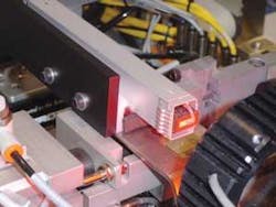
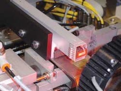
Lockheed Martin turned to custom production-equipment builder Advent Design for help in redesigning its phased-array assembly process. The latest part of this upgrade project involved redesigning the equipment used to assemble individual phased-antenna modules (phasors), replacing the manual-assembly steps with robot actions (see Fig. 1). Because the entire assembly was originally designed to be assembled by hand, the automated assembly system must have capabilities that closely mimic those of human assemblers.
“We decided to use vision primarily because we had to use the actual picture to determine where we were going to place additional components,” says Bill Chesterson, Advent CEO. “Generally, the clearances were less than the tolerances of the components we were working with. If we tried to mechanically align, say, the rivet for a horn spring with its hole, we would only get it right 50%-70% of the time.”
In a civilian manufacturing situation, the manufacturer would redesign the components for easy robotic assembly, then require its supplier to work to the new design. In the military setting, however, the new component has to be requalified, as well as the system that uses it, at a tremendous cost of time and money.
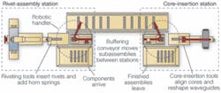
It was much less expensive to develop a vision-guided robotic assembler that could work with the existing qualified components. The assembly tasks are divided between two workstations: a rivet-assembly station (RAS) and a core-insertion station (CIS; see Fig. 2). The RAS has two work cells. The first attaches the horn spring to the waveguide with two rivets. The second attaches four rivets, two at a time, to the waveguide. These rivets are used to hold a connector block in place.
null
Waveguides are delivered to the RAS via an input conveyor. A robotic handler takes the waveguides and places them into a nest in the workcell for horn spring attachment. The system places rivets on an anvil and proceeds to place the waveguide over the rivets. A horn spring is then placed over the parts, and the rivets are stacked. The robotic handler transfers the waveguide to the second workcell, which inserts rivets, two at a time, into the predrilled holes and swages them in place. In other words, the tool compresses the aluminum surrounding the hole, squeezing it around the rivet to hold it in place. These rivets will be used later to hold a connector block in place.
The handler puts the riveted subassemblies on a transfer conveyor that takes them to the CIS. This transfer conveyor also acts as a buffer, accumulating up to an hour of production.
The buffering capability allows the two stations to work independently. If, as sometimes happens, the CIS is down for maintenance or repair, production on the RAS need not stop. The new subassemblies go into the buffer. On the other hand, should the RAS go down, the CIS can keep on working using subassemblies from the buffer.
At the CIS, a second robotic handler moves the next subassembly from the conveyor to a core-insertion tool. This tool pulls the waveguide sidewalls open to accept a core, inserts the core, and releases the sidewalls, clamping the core in place (see Fig. 3).
Vision-System Architecture
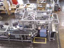
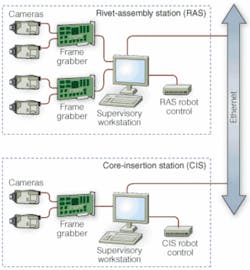
There are six video cameras plugged into three frame-grabber cards slotted into two supervisory computers to control the two stations (see Fig. 4). Each station has its own computer, and all stations communicate via Ethernet.
The vision systems are based on the Cognex VisionPro platform-a machine-vision software environment that engineers use to build applications to acquire images, analyze them, and pass the results to supervisory software written in Visual Basic, C++, or Microsoft’s C#. For this project, the Advent engineers chose CDC200 black-and-white digital cameras feeding into MVS-8100 frame grabbers plugged into Windows-based host computers. The supervisory software, which they programmed in Visual Basic, operates the servomotors and pneumatic actuators for each station through Allen Bradley Compact Logic PLCs. “There are about a dozen pneumatic axes and two to four servo axes for each of these assembly workstations,” says Chesterson.
It takes a number of inspections just to rivet a horn spring in place. To support horn-spring assembly, the RAS vision system must
- Check for presence of both rivets before the waveguide is placed on the riveting anvil
- Check that the waveguide is properly positioned before the horn spring is added
- Check that the horn spring is properly positioned before staking the rivets
- Check that staking has produced the correct formed rollover on the rivet head.
Checking for proper positioning requires making video measurements of the exposed portion of the rivet shanks. If not enough shank appears through the hole, the rivet has not been pushed through far enough, and proper staking will be impossible.
Checking the formed rivet head requires two measurements. There are specifications for both the formed head’s diameter and height. If both of these dimensions exceed the minimums, the rivet joint was made correctly. Otherwise, there is something wrong.
The RAS must also add four rivets and swage them to prevent their falling out during subsequent handling. To support this part of the process, the machine-vision system must
- Check for rivet presence on the fixture before inserting them into their holes
- Check to make sure the rivets are properly inserted before staking them
- Check to make sure that staking has compressed the aluminum to capture the rivets.
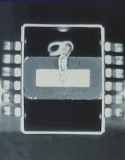
The tasks for the CIS vision system are more complicated. With the manual system, the operator aligned the core in the waveguide by centering a notch in the core’s edge in a hole drilled in the waveguide (see Fig. 5). This is a simple task for a human eye, but less so for machine vision.
The system uses a circle analysis algorithm to find the hole’s center. It then finds the rectangular notch’s center. The notch is not regular, so finding its center is not a matter of finding a point equidistant from the four corners of a regular rectangle. The VisionPro software includes an extensive library of vision tools and the programming environment QuickStart. Programming the analysis is a matter of picking the correct vision tools and applying them together via QuickStart.
Once the system has found the hole and notch centers, aligning the core becomes a closed-loop feedback problem. The computer calculates the vector difference between the centers’ positions and provides this information to the Visual Basic supervisory program. That program calculates the servomotor displacements needed to reduce the offset and sends them to the Aries Series servo slide and microstepper drive, which position the core to the calculated displacements. Then, the vision system rechecks the offset. If it is still outside tolerance, then the loop repeats. A second camera checks to make sure the core’s other end is properly centered in the waveguide’s horn end. This is a closed-loop feedback problem only slightly coupled to the problem of aligning the other end.
Each inspection task has its own lighting geometry requiring a separate lighting solution. In addition, the component finishes vary considerably.
“You could buy LED ringlights and things like that for vision lighting applications,” Chesterson points out. “In this case, however, we found it difficult to find off-the-shelf lighting that would work in the space available, so we developed our own custom LED illuminator. LED technology allows for compact and controllable lighting that greatly simplifies small-part illumination. With the addition of lenses, the lights produced an even, round spotlight. We typically use two per vision camera.”
Advent engineer Dave Sutton had used these lights in previous projects, so he knew their characteristics and what they could do with them. Sutton’s team found that these lights are small and easy to move around in tight positions, so that they can fine-tune the lighting.
The automated system has been successful in reducing the 2.5 operators that used the manual system to one operator. “These things are expensive,” Chesterson points out. They are too expensive to scrap if there is any defect. Rather than scrap a part that wasn’t fitted together correctly, they would rework it. “There was a lot of manual intervention to get the assembly process right, whereas now it’s automatic. With the old system, technicians had to manually adjust about 30% of the assemblies. Now that number is basically zero.”
Having the system divided into two stations with a buffer able to carry up to 60 minutes worth of RAS production has proved effective, as well. Without that feature, production would have to be halted frequently to replenish component supplies or for breakdowns of the complex machinery. The two-station system allows the production line to work through delays of up to 60 minutes, achieving an uptime record of well beyond 90%.
Company Info
Advent Design
Bristol, PA, USA
www.adventdesign.com
Allen Bradley
Milwaukee, USA
www.rockwellautomation.com
Cognex
Natick, MA, USA
www.cognex.com
Lockheed Martin
Moorestown, PA, USA
www.lockheedmartin.com
Parker Hannifin
Cleveland, OH, USA
www.parker.com
