Real-time operating systems simplify DSP-based imaging-system design
Real-time operating systems simplify DSP-based imaging-system design
By Bob Frankel
Performing imaging functions at video frame rates and greater is often beyond the capability of a single digital signal processor (DSP). Traditionally, these functions have been handled by custom application-specific integrated circuits (ASICs) that serve as slave coprocessors to the DSP. But newer DSPs such as the Texas Instruments (TI, Dallas, TX) TMS320C40 and the Analog Devices (Norwood, MA) SHARC are often capable of high-performance imaging, particularly when used in multiprocessor configurations. So, too, is TI`s TMS320C80, which provides a multiprocessor solution (four DSP cores) on a single chip.
Because of memory-space and performance constraints, DSP designers have traditionally balked at off-the-shelf real-time operating systems (RTOSs). But many of today`s RTOSs provide streamlined features that incur less than 2% overhead and occupy as little as 2 kwords of memory. Even overhead may be overstated because designers may have to include in their applications many of the features now provided by RTOSs in their applications.
Partition the application
RTOSs offer a number of functions for imaging applications. Among these are real-time multitasking, interrupt processing, intertask communications, memory management, and I/O. Real-time multitasking simplifies application development by permitting partitioning applications into modular, manageable pieces. Multitasking also boosts flexibility by enabling you to prioritize software functions for the critical parts of the application. Developing an imaging application as a collection of tasks also lets you target your application to multiple processors if the need arises.
RTOS interrupt services, when combined with multitasking, ensure real-time response for time-critical code while maximizing scheduling flexibility for background imaging tasks. In imaging systems, interrupt service routines (ISRs) provide the functions required to respond to asynchronous hardware interrupts (from an ADC, for example). ISRs, in turn, typically spawn RTOS tasks that initiate back-end processing such as FFTs and edge detection
Because interrupts for a particular device are disabled while ISRs are executing, ISRs typically perform only the minimum set of functions needed to recognize interrupts and acquire data, with execution times on the order of about 1-2 µs. Processing of blocks of image data is left to RTOS tasks, which typically have execution times in tens of microseconds.
To achieve additional scheduling granularity and flexibility, RTOS tasks can be further segmented into foreground signals and background tasks. Here, foreground signals have a lower priority than ISRs but a higher priority than background handlers, which may run for a millisecond or more.
To coordinate activity between multiple tasks and ISRs, RTOSs need to provide versatile interprocess communication and synchronization mechanisms such as mailboxes, semaphores, and queues. Mailboxes and streams provide a means for tasks to synchronize and communicate with one another through shared data structures. Semaphores and queues serve as a bridge between ISRs triggered by incoming device interrupts and program tasks awaiting signals from a semaphore.
RTOS I/O services also can help simplify image-processing development. But handling continuous data streams and large data blocks requires a transport mechanism that differs from that used by most RTOSs. Most RTOSs use the conventional read/ write paradigm to handle I/O. Developed for accessing file systems, this mechanism incurs redundant copy operations that reduce I/O speed and predictability. But streaming I/O functions provided by signal-processing RTOSs such as SPOX use a buffer-swapping approach to minimize unnecessary copy operations and ensure consistent delivery times independent of block size.
Multiprocessing support
Because imaging applications frequently span multiple processors, RTOS facilities for multiprocessing are essential. These should be an extension of the single-processor features provided by the RTOS. This simplifies development of single-DSP applications and allows migration to multiple DSPs without having to make source-code changes.
The key to transparently migrating an application to multiple DSPs is abstracting it from the hardware. Applications developed as a collection of tasks are easy to move because individual tasks need not be allocated to specific processors until run time. RTOSs can further simplify migration by providing device-independent I/O and interprocess communication mechanisms whose physical connections need not be specified until compile time.
One of the challenges of supporting diverse multiprocessor networks is handling data transfers and messages passing between nodes that aren`t directly connected. A DSP RTOS can address this by supporting dynamic data and message routing. This facility relies on intervening nodes to establish the necessary connections and pass data/messages along to the target processor.
Multilevel interrupt processing functions provided by a real-time operating system enable imaging system to provide real-time response for front-end image capture, while maximizing flexibility for back-end image processing.
DSPs and ASICs team to automate Pap tests
NeoPath (Redmond, WA) uses a combination of digital signal processors (DSPs) and imaging application-specific integrated circuits (ASICs) in its AutoPap 300 automatic Pap-screener system, a VMEbus-based image-processing system that automates Pap smears. In the AutoPap System, a video microscope, in conjunction with a TI 320C30-based capture and focus board, captures and digitizes microscope images. The image is then passed to 15 C30-based field-of-view (FOV) computers that interpret
cytological features found in the images. A host 68030 board running VxWorks specifies which algorithms the FOV DSPs should run and collects proces-sed data from the FOVs.
A SPARCstation provides the user interface and file system. A VxWorks COF (C30 Common object file) loader moves files between the SPARCstation`s file system and memory that is shared by the 68030/VxWorks controller and Spectron`s SPOX-based targets. The interface between VxWorks and SPOX is implemented via shared memory, semaphores, and interrupts.
In the AutoPap system, the DSPs serve as high-speed interrupt controllers, offloading compute-intensive imaging tasks to dedicated imaging ASICs. The capture/focus board and each of the FOV computers contains a C30 DSP, each of which runs a separate copy of SPOX.
The capture and focus board runs five SPOX tasks at three priority levels. These tasks handle dispatch, boot/exception, focus, strobe control, and interprocess communications. The FOVs run five SPOX tasks at four priority levels. These tasks handle task loading in response to host commands, double-buffering (so that one image can be loaded while another is processed), interrupt handling for the image-processing ASICs, and LED monitoring.
FOV imaging algorithms are written for the C30. But compute-intensive inner loops are offloaded to the ASICs that are configured by, and act as coprocessors to, the C30. Communications between the C30 and the ASICs are handled via interrupts, which occur at a rate of about 10,000/s. To keep pace with this interrupt stream, which requires responding to the interrupt and executing the necessary handlers, the C30/SPOX tandem must achieve an interrupt response time of 2 µs--a level that is beyond that of conventional microprocessors and real-time signal processors.
The system uses queues and semaphores to coordinate the processing of images. Mutual-exclusion semaphores provide resource lockout for shared resources such as look-up tables. This prevents the imaging ASICs from processing multiple images at the same time, an event that would result in image mixing. Queues provide a convenient means of sequencing the complex operations that are implemented in the imaging ASICs.
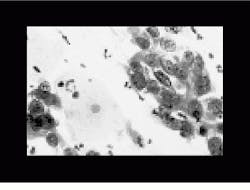
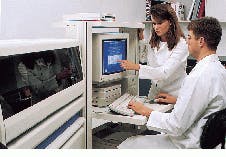
Automation of Pap smear results demands computers that interpret cytological features found in the images. NeoPath`s VME-based AutoPap 300 system captures and digitizes microscope images (top). After interpretation, the results are then displayed on the system console (bottom).
DSP-based imaging checks weld integrity
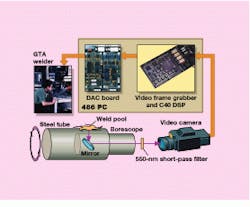
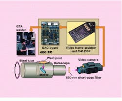
At Sandia National Laboratories (Albuquerque, NM), researchers have been experimenting with a DSP-based image-processing technique that controls a tungsten arc welder. The PC-based system, which uses a C40-based PC board from Data Translation (Marlboro, MA) running SPOX, analyzes weld integrity by monitoring the frequency of weld-pool oscillations.
The strategy is analogous to throwing a stone in the water and using the height of the wave ripples to determine the depth. By exciting the weld pool with an electric current and measuring the resonant frequency of resultant oscillations, designers can assess weld penetration and quality. A frequency of 30-50 Hz indicates full weld penetration, while 80 Hz indicates partial penetration.
In tungsten arc welding, a steady-state current of roughly 60 A creates the weld pool. The weld-pool oscillations are created by applying a 5-ms current pulse to the weld pool at a rate of
7 Hz. Light from the weld pool is sampled 256 times each time the pool is excited.
Oscillations are measured by using a solar cell to capture the white light emitted by the weld pool. The frequency of the oscillations equals the frequency of weld-pool oscillations. A solar cell is used instead of a photodiode because it provides a greater surface area (about 1.5-in.2 surface) that, in turn, provides a higher output voltage. The higher output voltage results in a better signal-to-noise ratio, which is critical for reliable operation in noisy welding environments. Another advantage of the solar cell is that its output is linear with respect to light intensity, which minimizes the signal-processing workload.
Voltage output of the solar cell is fed to an ADC on the Data Translation board. The resulting digitized time-domain data are then fed to the C40, which runs an FFT on the data to produce a frequency spectrum. The board then runs a peak-detection algorithm to identify the pool`s resonant frequency. This peak information sets the welder`s output current level.
The primary function of the SPOX in the system is to stream buffered data between the host and the C40 board and between the A/D converter and the C40. Data are streamed for about 0.125 to 0.5 s each time the pool is excited. This interval corresponds to the time that it takes weld-pool oscillations to die down.
Data from the camera are fed to a C40-based imaging board from Spectrum Signal Processing (Burnaby, Quebec, Canada), which operates on a 100 ¥ 100-pixel portion of the image. The board performs a thresholding operation to separate dark and light pixels, enabling the board to calculate the weld`s width, length, and area. This information is used by a control system that automatically adjusts weld current in real time to create the bead size selected by the welder.
Though low-frequency weld-pool oscillations provide a good quantitative indication of weld penetration and quality, the technique does not consider the back side of the weld. To address this, a boroscope is inserted into the cavity, and a digital video camera is pointed at the mirror. As soon as weld penetration occurs, light reflects off the mirror, enabling the camera to observe the back side of the weld.
Smarter IR camera guides unmanned vehicles
At Amber (Goleta, CA), designers have used a DSP/ SPOX-based platform to develop a smart IR video camera. Dubbed Radiance 1, the TMS320C31-based camera is aimed at applications ranging from unmanned vehicles to day/night surveillance, maintenance, and security.
The camera uses a gated threshold tracking algorithm to find and track objects. First, a tracking task defines a region of interest (also known as a gate) within the camera image. Then, a thresholding operation identifies hot spots (pixels above the threshold) within the gate. Finally, a centroid operation locates the target within the gate by finding the spatial mean of the hot pixels. The camera sends the centroid to a controller (that is, radar) via one of two serial ports at a rate of 50-60 times per second. The controller uses the centroid to position the camera and track the associated image.
To capture IR, the camera uses a 256 ¥ 256 indium antimonide focal-plane array. Amber selected this type of detector because it can resolve temperature differences as small as 0.025C.
The detector`s analog output is sent to a 12-bit ADC, and the digital output is fed to a 256 ¥ 256-pixel frame buffer. Images can be observed on the camera`s viewfinder, output to a monitor, downloaded to an attached PC`s hard disk, or stored on a local hard disk or 1-Mbyte PCMCIA flash card. The C31`s program is also stored on the flash card.
The C31 serves as the main controller, working in conjunction with a custom application-specific integrated circuit (ASIC). The ASIC normalizes the focal-plane detector outputs based on coefficients supplied by the C31. This is necessary because the voltage response of each detector is nonuniform for a given intensity. The response of each detector also varies with integration time (the digital camera equivalent of shutter speed).
The coefficients are derived by exposing the focal plane to a hot and cold reference sources. The gain and offset of each detector are then adjusted to produce a uniform field. A unique set of gain and offset coefficients are calculated for each of the camera`s four integration-time
options. These coefficients are stored in flash memory prior to deploying the
camera.
The ASIC also retimes the ADC`s 12-bit output to produce a standard 8-bit video output. While performing this, the ASIC also executes an AGC operation to adjust detector gain and image intensity. If the camera is looking at a hot object (lots of photons), then the ASIC backs off on detector gain, reducing image intensity. Coefficients required for this operation are supplied by the C3.
The C31 runs about a dozen SPOX tasks. In addition to coordinating overall program execution, the C31 runs normalization, tracking, autonomous operation, thermography, display, AGC, and serial communications tasks. Normalization and AGC tasks generate coefficients for the ASIC. Tracking locates centroids (hot spots) within a 64 ¥ 64 tracking window. Autonomous operation enables the camera to be operated unattended. Thermography calculates the temperature of the object being observed. Display controls on-screen symbology, while serial communications manages interrupt-driven communications between the camera and an attached PC.
Task scheduling is interrupt-driven. The tracking task keys off interrupts from the video and focal planes. Task scheduling is also priority based. The serial communications tasks has highest priority. Background tasks like the AGC task have the lowest priority. For the most part, tasks are autonomous; communication between tasks is minimal. Mailboxes coordinate infrequent data and message passing between tasks.
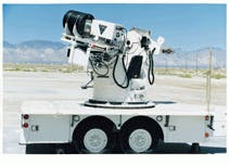
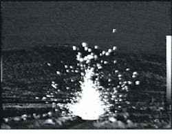
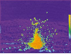
At the Naval Air Warfare Center (China Lake, CA), an Amber IR camera mounted on a trailer is used as part of the Metric Infrared Imaging System (MIRIS, top). MIRIS has been used to conduct impact analysis of shell fragments from 25-mm steel bullets after they strike armor plate (middle). In the analysis, original IR and pseudocolored IR images are used to highlight results (bottom).
