Vision and robots rack auto parts
Andrew Wilson, Editor, [email protected]
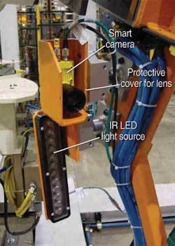
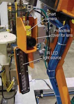
In October 2006, the Automated Imaging Association (AIA; Ann Arbor; MI, USA; www.machinevisiononline.org) held a workshop on vision and robots for automotive-manufacturing applications in Novi, MI, USA. Perhaps the most informative presentation at the conference was that by Valerie Bolhouse, technical leader for machine vision in advanced manufacturing technology development at the Ford Motor Company (Detroit, MI, USA; www.ford.com). In her presentation entitled “The dos and don’ts of establishing a successful vision project,” Bolhouse outlined the development of a vision-guided robot system for automatically racking parts after they have been assembled (see Fig. 1).
“After assembly,” says Bolhouse, “each part must be loaded into a dual-sided rack, each side of which accommodates seven arms that each hold seven parts.” With parts being loaded approximately every 30 s, it takes approximately one hour to load a full rack with 98 parts. To do this, robot mounted cameras are used to locate the hooks on each of the racks and verify the rack’s integrity. Parts are then picked and guided onto these racks in a repetitive manner until the rack is fully populated.
“It is vitally important to identify any hurdles to a possible implementation early in a project’s development,” says Bolhouse. “After demonstrating a system using standard parts and racks, it was determined that the system requirements were initially beyond the capability of the robot even with vision-guided capability.”
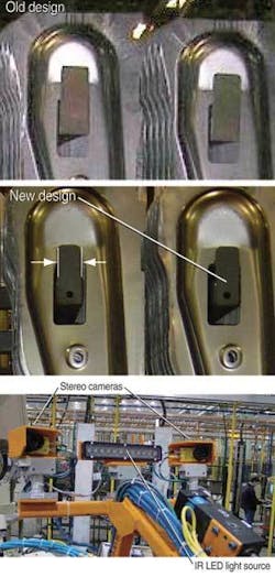
Since the racks were originally intended for manual loading, the tight 2-mm hole-to-hook clearance was too small, and there was no way for a vision system to reliably locate them to accommodate automated part loading. Because these problems were identified early and the racks needed refurbishing, they could be redesigned to be “vision-friendly.” This was achieved by reducing the hook in size to improve clearance and adding fiducials to be used as vision targets to locate hook positions, even as the hooks become misshapen and corroded in use (see Fig. 2).
Fiducials were also added at the lower part of the rack to ensure that the part fits between the guides on the rack. To image these fiducials, three smart cameras from Cognex (Natick, MA, USA; www.cognex.com) were mounted on a Kawasaki robot and connected via Ethernet to an industrial PC which was in turn interfaced to the robot controller.
“Although they are more expensive than standard VGA cameras, smart cameras allowed a single high-flexibility Ethernet cable to be used in place of more fragile video cables,” Bolhouse says. The vision cameras learn their relationship to the robot through a series of moves about a fixed calibration target in the cell.
To illuminate these targets and the fiducials on the racks, a high-power near-IR LED lightbar was used. “By using IR radiation outside the visible spectrum,” says Bolhouse, “the fork-lift truck drivers are not blinded by high-power LED lights as they load and unload the racks into the robot workcell.”
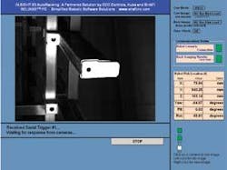
Because the system was designed to be operated by plant personnel, all information displayed on the operator’s screen relating to pixels and gray-scale image information was removed. Instead, a simple operator interface was developed that could be used to quickly identify problems (see Fig. 3). “In designing such systems,” says Bolhouse, “local work rules can dictate how the solution is implemented. For example, while an operator may be allowed to use the controls on a touch panel, only a UAW electrician can touch the robot’s teach pendant.”
Other valuable lessons were learned in the process of developing the system. “It is vitally important to validate the system’s performance outside of the specification limits, that is, see what it takes to break it,” Bolhouse says. “Also, never underestimate that timing is a critical and often underestimated factor. Because integration of the vision system could only be performed after all the other functions of the workcell were integrated and debugged, adding vision capability was blamed for all the time delays associated with the project!”


