Robot system reduces operating costs
Work cell that uses a robot coupled with a vision system provides robot guidance in the automotive industry.
By Richard Meyer
Len Industries, which produces precision parts for the automotive industry, approached FANUC Robotics America for a robotic solution to unloading—or depalletizing—randomly placed transmission gears from a plastic bin. At the time of the request, the gears were manually unloaded, and Len Industries wanted to reduce labor costs and increase throughput by automating the process.
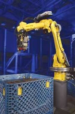
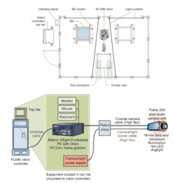
FIGURE 1. In a depalletizing work cell, a FANUC M16iB robot triggers the visLOCi vision system with JAI PULNiX TM-200 camera to take a snapshot of transmission gears to determine their offset from a predetermined stand-off height and conveys that offset to the robot controller.
In response, FANUC designed a work cell that uses a FANUC M-16iB robot coupled with a FANUC visLOCi vision system for robot guidance (see Fig. 1). The vision hardware includes a JAI Pulnix TM-200 video camera, an Advanced Illumination RL36120 red LED ringlight, high flex camera power cable, high flex camera coaxial cable, power supply, and Matrox 4Sight-II computer. The Matrox computer includes an Orion PC104+ frame grabber, which captures the vision information. A generic flat-panel monitor, keyboard, and mouse complete the user interface to the vision system. Other major components include a custom-designed and built end-of-arm tool (EOAT), pneumatics package, robot riser, two-part rack locators, divider sheet storage rack, interface panel, and safety fence.
Multitasking robots
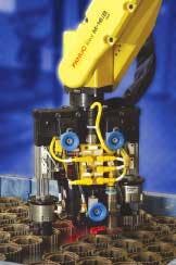
In addition to unloading the gears onto an exit conveyor, the robot must transfer a plastic board that divides each gear layer. Each bin, measuring 746 × 686 × 721 mm, holds 22 layers with 88 gears to a layer. To meet the throughput requirements of the work cell, the vision-guided robot needed to reach an average cycle time of 4.5 s per part, including the removal of the plastic divider sheets. Therefore, FANUC engineers designed the system to transfer two parts at the same time using an inner-diameter grip end effector with two gripper modules (see Fig. 2).
The application must also depalletize two different types of transmission gears. While each of the gears have the same inner and outer diameter, they differ in height. The gears are manually loaded into the bin with random orientation and positions, thus requiring vision to locate and transfer the parts.
An order to everything
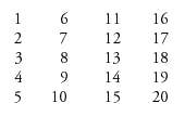
The visLOCi vision program resides on the Matrox computer, and the computer and the robot communicate over Ethernet ports, which are standard on both. The robot moves to an area above the bin and begins the vision process on the PC by reporting the total number of targets found in the field of view and the locations of the targets (see Fig. 3). The bin is divided into 20 robot zones for taking snapshots of gears. Each bin is arranged in some variation of the pattern
null
The center zones are emptied first, and the perimeter last in order: 9, 7, 14, 12, 8, 13, 3, 6, 17, 19, 10, 2, 11, 18, 15, 4, 1, 16, 20, 5. Emptying the center of the bin first reduces part-to-part pressure, which in turn reduces pressure between parts and lowers the possibility of turning a gear on edge when lifting an adjacent part. After the inside parts are picked, the zones skip around each other to avoid picking parts in adjacent zones. Adjacent zones are avoided to eliminate the possibility of moving the second part to be picked while picking the first part.
FIGURE 3. In the FANUC robot guidance work cell at Len Industries, the Top Hat/RJ3IB Robot Controller sits just outside the work area and includes a Matrox 4sightII industrial PC to operate the visLOCi image-processing program. The junction box provides a break point for the coaxial and power cables.
Parts that are identified on the wall of the bin (the outer ring of parts) are moved toward the center of the bin before any upward movement. The center move prevents the parts from being stripped off the EOAT by interferences with the bin walls.
FANUC Robotics chose to mount the Advanced Illumination RL36120 red LED ringlight source on the robot because red light is often used in combination with a red light filter at the camera to negate the disruptive affects of ambient light. The system is located near a large bay door, and, whether it is day or night or the doors are open or closed, ambient light does not affect the operation of the system.
A 16-mm camera lens mounted to a gray-scale camera takes photos at a stand-off height (distance between the camera and the gear) of 712 mm. Images are transferred by coaxial cable to the Orion PC frame grabber, where they are digitized. The camera is mounted to the robot arm, allowing the 712-mm stand-off height to be maintained throughout the entire bin. The 16-mm lens and the stand-off height of 712 mm were selected to keep the camera height above the walls of the part bin, from the top layer (721 mm above the bin) to the bottom layer (10 mm above the bin). The field of view is 287 × 215 mm, and pixel resolution is 0.374 mm, providing enough accuracy to reliably pick the gears.
Software interface
Calibration is critical to robot-guidance applications. The vision system must be calibrated so that it can calculate feature scaling and robot position in a 2-D environment. In this application, visLOCi is calibrated from a grid of a series of circles with known sizes and dimensions. The system is only calibrated when hardware is changed or damaged. When required, the fixture-mounted calibration grid is placed within the bin positioning locators (the space where the bin usually sits). The known dimensions of the circles provide the scale in millimeters/pixel. The same grid in the exact same position teaches a robot frame. Teaching the robot frame calibrates the robot to the vision system. The values taught to the robot calibration frame are uploaded to the vision process on the Matrox PC, and the offset position is calculated relative to this frame.
The robotic system is trained using the Windows-based visLOCi program, with the dedicated Matrox computer providing access to the vision system and immediate ability to program new transmission gears and troubleshoot vision issues. A geometric pattern-matching algorithm automatically finds the parts for which the system has been trained.
VisLOCi calculates and provides the robot with the x and y location of the center of the gear with respect to the trained nominal position. Both types of transmission gears are symmetrical, and so radial orientation is not required. VisLOCi interfaces directly to the robot via Ethernet through the robot server. The offset data from visLOCi are placed into position registers on the robot, and no third-party communication or interface software is required. The robot interprets the x and y information as an offset applied to the nominal position.
Locator parameters are input and monitored in the visLOCi program. These parameters are used to provide a range of findings that determine if a part has been "found" or "not found." The key parameters used in this application are size and contrast. The size and contrast are combined to create an overall score that determines if a part has been found. Utilizing the size characteristic, visLOCi can establish if the imaged part is on the current layer or visible one layer lower. Contrast can be used to differentiate between an actual part and an oil ring from a part that has been removed.
For example, during testing, the vision system identified phantom parts that were caused by oil rings on the plastic board. The problem was solved using the contrast-locator parameter. On a contrast scale of 1 to 100, the oil ring scored a contrast value of 44 versus a contrast value greater than 95 for actual parts. Phantom parts were eliminated by adjusting the overall part score to be higher than the lowest oil ring score, in this case 44.
The vision system also located gears that were one level lower than the level the robot was unloading. The parts were on the outer ring, and the plastic board allowed enough of the part to be imaged so that visLOCi identified it as a "found" part. The problem was resolved using the "size" locator parameter to ignore parts that were not at least 95% of the trained part size.
Getting results
After the system was installed, Len Industries requested the addition of a function to detect part orientation. Gears that enter the machining center upside down cause damage and downtime for the tool. Using a clockwise-pointing-part feature, visLOCi was able to identify upside down parts and load these parts onto a reject chute. The parts are then manually loaded to the tool.
Len Industries also requested improvements in the visLOCi display tools that would show the operator the edges the vision system was using to locate a part. In response, FANUC Robotics added red and green indicators on the image in the visLOCi interface. The green edges show a positive edge find and the red edges indicate where an edge was expected, but not found.
After four months of operation, Len Industries estimates that the vision/robot cell increased production throughput by 5% and decreased labor costs by 30%, with a system uptime greater than 90%.
RICHARD MEYER is project manager, FANUC Robotics America, Rochester Hills, MI, USA; www.fanucrobotics.com.
Company Info
Advanced Illumination, Rochester, VT, USA, www.advancedillumination.com
FANUC Robotics America, Rochester Hills, MI, USA, www.fanucrobotics.com
JAI PULNiX, Sunnyvale, CA, USA, www.pulnix.com
Len Industries, Leslie, MI, USA, www.len-ind.com
Matrox, Dorval, QC, Canada, www.matrox.com
