Vision-based robot/human Ping-Pong
Twenty years ago, Russell Andersson, a member of technical staff of the Robotics Systems Research Department at AT&T Bell Laboratories (Holmdel, NJ, USA; www.research.att.com), constructed a system to play Ping-Pong using a real-time vision system (see “A Robot Ping-Pong Player--Experiments in Real-Time Intelligent Control” by Russell L. Andersson, MIT Press, http://mitpress.mit.edu/catalog/item/default.asp?ttype=2&tid=4218). At the time, this was a particularly difficult task that employed sophisticated image-processing software, VLSI devices, and a distributed network of computers. Seven years ago, Fumio Miyazaki and his colleagues at Osaka University (Osaka, Japan; www.osaka-u.ac.jp) also built such a system using locally weighted regression theory that allowed the robot to learn from previous practices to continuously increase its skill. “However,” says Homer Liu, director of the R&D department at QuantaView (Kawasaki, Japan; www.quanta-view.com), “the robot was still incapable of performing with the skill of even an untrained human being.”
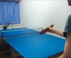
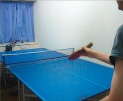
Recently, because of the increase in processing power of PCs, commercially available computers can fulfill the image-processing and control tasks of automating the game. Indeed, Liu and his colleagues have developed a system using off-the-shelf components, which, one day, he expects will be fully commercialized (see Fig. 1).
The system is based on a selective compliant articulated robot arm (SCARA), a four-axis robot arm that that can move to any x-y-z coordinate and uses a fourth axis of motion as a wrist rotate (theta-z) function. “Although the center of the paddle can only move inside a plane parallel to the surface,” says Liu, “in principle, the arm can return Ping-Pong balls to any desired angle.”
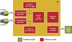
Two Intel Xeon processors running at 3.2 GHz are used to control the system. To make full use of the CPU power, Intel’s Integrated Performance Primitives (IPPs) are used as the basis for the image-processing software. Two Marlin cameras from Allied Vision Technologies (Stadtroda, Germany; www.alliedvisiontec.com) with FireWire interfaces digitize stereo images into the host PCs. These 640 × 480-pixel cameras, running at 60 frames/s, are synchronized by an external clock operating at 60 Hz. This same clock also triggers specific image-processing functions (see Fig. 2).
A method developed by Zhengyou Zhang of Microsoft Research (Redmond, WA, USA; http://research.microsoft.com) is used to calibrate the cameras. “This technique only requires the camera to observe a planar pattern shown in at least two different orientations,” says Liu (see “A Flexible New Technique for Camera Calibration,” Microsoft Research Technical Report; www.research.microsoft.com/~zhang/Papers/TR98-71.pdf). Since only orange Ping-Pong balls are used, balls can be separated from the background image by computing the color in hue, saturation, and value color space. The center of the ball is defined by its center of gravity.
Because the robot needs to take action as soon as possible, each frame of the image data has to be processed within 1/60 s. Thus, each camera has its own processing thread, efficiently balancing two Xeon processors. In operation, 3-D ball-track-generator software calculates the ball track according to the 2-D coordinates from each camera. Both the time and position of the ball when it hits the Ping-Pong table are predicted using aerodynamical theory. Since the robot arm can only move within the plane of fixed height from the table, the hit positions are decided where the ball tracks cross 22 cm above the table.
Trajectory builder software calculates the trajectory of the paddle in real time. The trajectory must be as smooth as possible to reduce motor torque and to obtain stable performances. A PCI-7404M motion-control board from Interface Corp. (Hiroshima, Japan; www.interface.co.jp) controls the servomotors of the robot in real time. Sequences of events from the trajectory builder are sent to an on-board command buffer of this board executed upon command.
“By storing the motion program in the buffer, the host PC is free to perform other tasks such as data acquisition,” says Liu. “Although the calculations are not strictly scheduled because Windows is not a real-time operating system, the on-board buffer allows the robot to perform in a smooth and continuous manner.” Because of torque limitations of the motors, fast balls returned by the robot’s human opponent cannot be handled by the robot. However, the robot can return balls from those with beginner skill level. QuickTime movies demonstrating the Ping-Pong robot can be found at www.quanta-view.com/productEn.html.


