Polarization in imaging: Things you did and didn’t know it could do
Kevin Harding
Polarization is a property of how light energy propagates. It is not the same as color, where selecting and viewing different bands is possible. When filtering out a color, that band of light becomes unavailable, but with polarization, the state of the light repeatedly changes. In fact, every time light reflects or passes through something, the state of polarization of the light changes.
The machine vision community has known for years that polarization enables the filtering out of glare from a shiny surface, but there are many more tasks suitable for polarization.
Glints and reflections
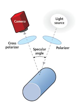
Figure 1 shows a typical application of polarizers, with a polarized light source and a second polarizer placed in front of the camera.
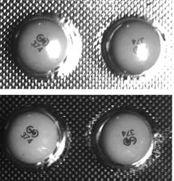
Any specular reflection, such as glint off a bubble pack (Figure 2), is reduced or removed, providing a better view of the pill beneath. Clear surfaces like the bubble pack—where reducing specular or mirror-like reflections help an application—aren’t the only suitable use for polarization.
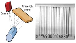
Figure 3 shows a barcode on a can where the shiny surface of the can makes it impossible to read the alphanumeric number under the barcode. Using crossed polarizers, however, makes the number easily readable without making the rest of the image dark.
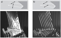
Polarization can change based on the material and angle of incidence of a part surface to suit different applications. For example, Figure 4 shows light illuminating a corner reflector formed by two shiny metal surfaces at a right angle. Two reflections of the light, as shown, cause a rotation of the image. If the incoming light was polarized at -45°, then upon reflection, light polarizes at +45°. To reject the specular reflection, the second polarizer needs to align parallel to the first one. The diffusely reflected light in the example becomes depolarized so it is visible.
Thin coatings, changes in thickness, strain effects
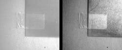
The previous example represents just the beginning of what can be done with polarization, however. Figure 5 shows a piece of clear tape on a metal surface. The image on the left shows visible tape with low contrast, while on the right, polarization causes the tape to stand out.
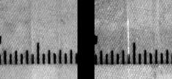
Edges can also be made more visible using polarization, as shown in Figure 6a. The left side of the images shows a nearly-invisible edge of a piece of tape on a clear plastic ruler. With different polarization, the edge stands out, as seen in Figure 6b.
Plastic parts, such as the lid in Figure 7, often contain stresses that can be mapped using polarization, which helps to identify potential breaks in the container. A whole field of non-destructive testing referred to as photo-elastics models stresses in a part design by making a part out of plastic and analyzing the model using polarized light.
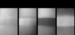
The polarization effect also changes with a coating on the plastic or a change in thickness (Figure 8). On the left, a change in the thickness of the ruler is not evident, but on the right, with just a change in polarization, stress lines change abruptly, indicating a change in the mechanical integrity of the ruler or in this case, a change in the thickness of the plastic.
Changes in slope
Perhaps less known, polarization can help determine slope and pitch of a surface. Highlighting slope using polarization requires a setup like that shown in Figure 1, with the biggest difference in setup being that—when rejecting a simple specular glint with cross polarizers—it is best to keep the polarized light source and camera with a polarizer on the lens close to each other and near normal to the part surface. By keeping both source and viewing point close, the polarization of the light changes relatively little upon reflection so it can be most effectively rejected by the second polarizer (analyzer) by crossing it relative to the illumination polarization. Effectively, the glint approach rejects the well-polarized, specularly-reflected light and passes the diffusely reflected, non-polarized light.
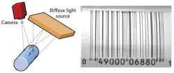
To highlight the slope using polarization, the light reflected from the surface must be polarized over the area of inspection. To do so requires a bright field arrangement lighting the full surface bright. Figure 9 provides an example, where a broad, diffuse light illuminates the barcode from Figure 3 rather than using polarization. Such bright light methods are often used with shiny surfaces for providing a brightly-illuminated surface to look for defects, printing, or other surface features—a common method when a shiny surface has a lot of shape, which results in a lot of bright and dark areas. Without a shiny surface, the reflected light will not maintain polarization and will not be useful for seeing slope changes. The surface does not need to be mirror-light either, as any shiny surface (bare metal, painted surfaces, for example), maintains much of the polarization of the light.
Common bright field illumination tools include using a diffuse light source such as a light box, and in-line diffuse light in front of the camera, a diffuse ring light or a light tent (sometimes called a cloudy day illuminator). A diffuse light from multiple directions would typically not provide a consistent polarization of illumination light and would not be useful for highlighting slopes.
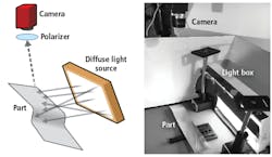
A bright field arrangement using a light box off to the side is shown in Figure 10. A higher difference in the angle between the illumination direction (light box) and the analyzer direction (camera) produces more change in the polarization state upon reflection—a technique used in advanced instruments such as ellipsometers for analyzing thin film coatings.
The high-angle reflection is not the same as the double-bounce reflection in Figure 4 where the polarization rotates 90° and maintains a linear polarization because of the retro-reflection acting as a normal incidence reflection. Figure 10 represents a single reflection, where the source and camera relative to the part should be positioned so that the entire surface appears bright. The initial linearly-polarized light becomes elliptically polarized, changing with the angle of the surface both in and out of the plane of incidence (the plane containing both the illumination and viewing directions). This change in polarization can be seen by rotating the polarizer in front of the camera.
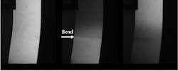
Figure 11 shows three different polarization states of light viewed from a bare sheet metal part with subtle bends. In the first image on the left, very little change in light level is seen across the part. Changing the polarization seen at the camera by about 45° shows a change from the top section to the bottom section, but not a lot of change from top to middle. Changing the polarization seen at the camera further, the next-right image shows the middle section to be a much different slope. Turning the part over in the far-right image reversed the shading because the slope is reversed. Nothing else changed in these images except the polarization seen by the camera.
Figure 11 does not show shading due to changes in illumination angle. The first image on the left shows shading effect, which would not be very useful in reliably detecting slope changes. Slope changes are perpendicular to the light direction coming from the right, with an identical illumination angle in all three images. A big change in brightness due to the change in polarization state reflected from each region across the part to the bottom still exists, however.
Such an effect proves useful on curved surfaces as well, creating a shading effect where doing so with the light angle alone is not practical. Figure 12 shows a curved sheet metal part illuminated by a broad, diffuse light from the side. No real indication of shape exists without polarization, but with a polarizer over the light, another in front of the camera the shading can be placed on the positive or negative slope of the curve of the part. In addition, a small, otherwise imperceptible edge bend can be seen near the center of the part.
Such a capability proves useful for many curved parts, including sheet metal panels on a car or a casting where the orientation of the curve may not be known or using a large directional light may not be practical for shading based on lighting angle.
Summary
Polarization offers additional and sometimes unique capabilities for a machine vision lighting system. As with any lighting, polarization does not provide the answer to all applications, but for applications that may have:
· multiple reflections,
· specular glints,
· thin coatings or thickness changes,
· strain effects or
· subtle slope changes that are hard to see,
polarization provides an extra tool in the machine vision lighting toolbox.
References
1. Kevin Harding, “Machine Vision Lighting,” in The Encyclopedia of Optical Engineering, B. G. Batchelor, Ed. Marcel Dekker (2000).
2. L. B. Wolff, “Surface orientation from polarization images,” SPIE Proc. Vol. 850, p. 110 (1987).
3. R. M. A. Azzam, N. M. Bashara, Ellipsometry and Polarized Light, North Holland, New York (1987).
4. Max Mark Frocht, Photoelasticity, John Wiley and Sons, New York, Vol.1 (1941) Vol. 2 (1948).
Related stories:
Understanding unique machine vision illumination methods
Fourier-transform analysis helps optical method improve RA detection
Moiré imaging methods enhance 3D image generation in machine vision
Share your vision-related news by contacting Dennis Scimeca, Associate Editor, Vision Systems Design
SUBSCRIBE TO OUR NEWSLETTERS
