Machine vision aids engine assembly
Intelligent cameras team with RFID to check placement of automotive flywheels, pulleys, and screws.
By Birgit Gottsauner
As a joint venture between Mitsubishi Motors and DaimlerChrysler, MDC Power manufactures three- and four-cylinder 1.1-, 1.3-, and 1.5-liter aluminum cylinder-block engines for vehicles such as the Mitsubishi Colt. Each engine version can be manufactured with an automatic or manual transmission, which determines the type of flywheel used. To automate the inspection of these engine blocks, IIM helped develop a system to visually inspect completed engine subassemblies to ensure correct parts placement.
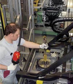
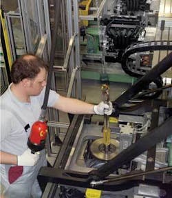
Because numerous types of engine are manufactured at the plant, a variety of matt or glossy screws of different lengths and washers of different types must be used to mount belt pulleys and flywheels to the engine assemblies (see Fig. 1). Which engine requires what combination of these parts is stored on a radio-frequency-identification (RFID) tag-part of the MOBY I RFID system from Siemens-which is fixed to the workpiece pallet containing the partially assembled engine block. At each assembly station this RFID tag is read out and its data displayed on an operator console.
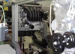
After each engine block has been assembled, the integrity of the screws, pulleys, and flywheels is measured using two Simatic VS 721 intelligent cameras from Siemens (see Fig. 2). Because the RFID on the work pallet contains the correct parts list for each engine type, it is used by each of the cameras to identify a list of known good golden template images that are stored in each of the cameras. Simple image-processing tasks such as outline checks, pattern-matching, position identification, and 1- and 2-D barcode reading then identify specific parts of the engine assembly (see Fig. 3).
Since extraneous light at the test stations could not be reduced, a camera-triggered red ring flashlight is used to illuminate each engine assembly. Should screws or washers be missing or be installed incorrectly or the wrong way around, this lighting will produce images with different shades of gray off the matt-black or glossy metallic surfaces. Whether the proper belt pulley or flywheel has been mounted for each respective engine version is determined by comparing the outline of the reflected images and the light and shadow areas with a golden template image.
If the target image and the actual image show a match of at least 98%, the system assumes that all components are present and have been assembled properly, otherwise the engine is automatically sent for rework. So that the operator can easily visualize the cause of the error, the test result from the camera is written back to the operator’s console and displayed in plain text, such as “screw missing.” The data are stored in the history record of the engine, allowing the entire assembly process to be reconstructed later.
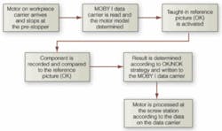
FIGURE 3. The source of all analyses is an OK picture. In the OK picture, the areas to be checked are marked. The markings can be geometric shapes such as circles, rectangles or polygons. The areas enclosed by the markings are resolved in shades of gray. With color cameras, information is extracted via RGB selection. The markings are related to each other via radii and angles. If an actual picture is then recorded, the geometric shapes present are compared to the gray shades or color values in the shapes (areas to be checked) determined in the OK picture via the positions of the shapes (radii and angles). If they agree (within a tolerance), the status OK is output; if the specified tolerance is exceeded, a NOK (not OK) assessment will result. The permitted tolerance between the OK picture and the reference picture is dependent on the application.
“In rare cases, the cameras may report errors where actually there are none; for example, if individual screws turn out slightly more matt or glossy,” says Uwe Nitschke, assembly production engineer at MDC Power. “But such errors are better than unrecognized errors, which would have far greater implications later in the production process.” In these isolated cases, the operator must rapidly visualize captured images and perform a manual inspection. “The technical prerequisites for this have already been met and will be implemented in a second phase of system development,” Nitschke says.
Because every VS 721 features an integrated industrial Ethernet interface and is connected via Profibus DP to a Simatic S7-317-2 DP system controller, it is possible to transmit live images from the camera to the operator’s monitor without additional software. Remote diagnostics can be performed by interfacing a notebook or a PC using an Internet browser to the TCP/IP address of the camera system.
MDC Power is satisfied with the automated vision system deployed at the engine-assembly plant. “The price/performance ratio is right, and the cameras have been working flawlessly from the beginning. Interruptions at the subsequent processing stations due to unrecognized assembly errors have been reduced to almost zero,” says MDC’s Nitschke.
BIRGIT GOTTSAUNER is in marketing at Simatic Sensors, Siemens Automation and Drives Division (Nürnberg, Germany; www.siemens.com).
Company Info
DaimlerChrysler
Stuttgart, Germany
www.daimlerchrysler.com
IIM
Dillstädt, Germany
www.iimag.de
MDC Power
Kölleda, Germany
www.mdc-power.de
Mitsubishi Motors
Tokyo, Japan
www.mitsubishi-motors.com
Siemens Automation and Drives Division
Nürnberg, Germany
www.siemens.com


