High-speed inspection system finds defects in steel
Antonio Cruz-Lopez, Alberto Lago, Roberto Gonzalez, Aitor Alvarez and José Angel Gutiérrez Olabarria
To produce seamless steel tubes, a steel billet is transported into a furnace where it is first heated. Next, the billet is pierced to form a thick-walled hollow shell, after which a mandrel bar is inserted into the shell. The shell then undergoes elongation rolling in a mandrel mill. Following the elongation process, the billet is conveyed to a push bench, where it is pushed through a series of roller cages. The result is that a hollow length of steel tubing with consecutively smaller wall thicknesses is formed.
As effective as the hot rolling process is, the roller cages in the push benches can sporadically produce marks and defects on the surface of the steel that are extremely difficult to detect in hot conditions. Hence, in their quality improvement programs, many manufacturers look to identify such defects as early as possible to avoid producing tons of defective material at considerable expense.
Vision system
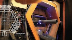
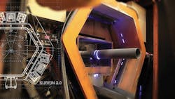
To resolve those issues, engineers at Tecnalia (Derio, Bizkaia, Spain; www.tecnalia.com) have developed a machine vision system dubbed Surfin' that can enable steel manufacturers to detect such defects as the steel emanates from the push bench (Figure 1). The detection of such defects provides manufacturers with an indication of any issues in the production process, enabling them to perform preventative maintenance on the push benches at an early stage and preclude any defective steel tubes from being delivered to their customers.
The typical defects found on the surface of such tubes generated by the roller cages usually follow a repetitive pattern and continue to appear until the rolling stands are changed. They can include tears or rips in the surface, rolling stand blocking marks, cracks and detached steel which is later pasted onto another part of the surface of the steel tube.
The challenges faced by the developers were not trivial. The conditions in such a production environment are extreme. Not only are the steel tubes produced at a relatively high speed of 6-7m/sec (Surfin' can work up to 10 m/sec), the temperature of the steel as it emanates from the roller cages is about 1000°C. Compounding the inspection problem is that the environment is dirty and water and oil vapor are present.
As the hot surface of the steel radiates light that is directly related to thermal emission in the IR, red, orange and yellow bands, capturing an image of all the light reflected by the surface would saturate the sensor in a camera, since the camera would be sensitive to all the radiation emitted by the steel tube. To solve this, the Surfin' system (patent ES2378602 and EP2341330) uses light of a wavelength far from the emitted spectrum of the incandescent steel.
Images that reach the cameras in the system are then optically filtered with a narrow optical band-pass filter from Edmund Optics (Barrington, NJ, USA; www.edmundoptics.com) centered on 470nm with a width of 10nm and an infrared (IR) radiation filter. Both filters enable the CCD cameras to only receive radiation in the desired wavelength band, while the incorporation of the IR filters protects the electronic systems from heat radiation. The controlled lighting technique allows the system to capture images of the entire surface of the tube as if it were cold.
To enable the system to capture a 360°image of the surface of the steel tube, the system uses three sets of 14.000 lines/s Teledyne DALSA (Waterloo, ON, Canada; www.teledynedalsa.com) Spyder 3 line scan cameras that are mounted at 120° intervals perpendicular to the plane of the rolling steel shaft in protective enclosures around the output of the push bench. In a former version of the system, two powered 200mW 473 nm blue laser light sources from Laserglow Technologies (Toronto, ON, Canada; www.laserglow.com) are employed on both sides of each camera to illuminate the surface of the steel with dark field lighting. As a result of the geometry of the system, it is possible to capture a complete image of the tube continuously and in real-time (Figure 2a and b).
Because of the temperature of the environment, it was important to keep the cameras cool continuously. To do so, compressed cooled refrigerated air is injected into the protective enclosures to protect the camera and laser equipment from the heat and the harsh environment. Not only does the air cool the systems, but excess air is then expelled through a window through which the lasers project their light beam and the camera captures the image, preventing the deposition of scale, oxides, dust and liquids.
Image processing
Once the images of the surface of the steel are captured, they are transferred 100m to a PC-based server in the control room over an optical fiber Gigabit Ethernet link. Here, the images are first pre-processed to enhance the contrast of the images with custom built image enhancement algorithms such as histogram equalization. Since the usable data in the original images are represented by close contrast values, the technique increases the global contrast of the images.
Having enhanced the images, they are then processed using custom built software which, in a previous version of the system, employed an assisted learning system based on Support Vector Machines (SVMs). Once the system has been taught to learn specific defects from different examples by texture, contrast, and size, the algorithm can then automatically detect and classify the most important production defects in the production environment (Figure 3).
The PC-based server used to store the images from the cameras together with data of the defects found and their locations on the tubes also stores alarms for pressure, temperature, speed signal, communications, and other tube production data in an Oracle database for quality control and traceability. It is also possible to perform remote inspection of the data on the server by installing a client application on a computer connected to the company LAN.
Since the system was originally developed, it has undergone several enhancements. While the basic concept behind the system has been retained, much has been improved. The structure of the system has now been redesigned to enable the alignment and the adjustment of the cameras and the lighting to be adjusted more easily.
Newer versions of the system have also adopted a liquid, rather than an air refrigeration technique to enable both the lighting and sensors to be placed closer to the steel tubing and to allow hotter or larger steel sections to be imaged. LED light sources from Metaphase Technologies (Bristol, PA, USA; www.metaphase-tech.com) have also replaced the earlier lasers, leading to an increase in lifetime of the light sources from 2000 to 50,000 hours, and eliminating artifacts such as speckle that can corrupt the images captured by the cameras.
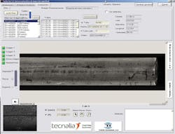
The software user interface has also been improved, enabling plant operators to visualize the position and the specific nature of the defects on the steel as they occur (Figure 4). It is now also possible to store months of production data on the database, allowing plant managers to review the periodicity of any errors that might be occurring and to schedule regular preventative maintenance operations. The system can also support many users who can not only access the system locally but over the Internet as well.
Change in classification
Perhaps the most important recent development to the Surfin' system, however, is the replacement of the older SVM-based classifier by an in-house developed candidate window detection stage and a Convolutional Neural Network (CNN) for defect classification. CNNs can learn to extract the relevant features that characterize each type of defect from the training images and perform classification, while an SVM only maps its input to some high dimensional space where the differences between the classes of defects can be revealed.
By assuming that all objects of interest-such as the defects-share common visual properties that distinguish them from the background, the candidate window detection stage outputs a set of regions that are likely to contain those defects. A Convolutional Neural Network (CNN) then extracts the learned features and performs the actual defect classification on the image data.
The CNN classifier was validated over a custom image database with defective hot tube images, and it was discovered that the deep learning-based approach significantly outperformed the earlier SVM Classifier by decreasing both the number of false positives and false negatives that were detected.
The most relevant performance metric when performing 2-class classification (as in defect versus no-defect) is the AUC, or Area Under the ROC (Receiver Operating Characteristic) curve, which is built by plotting the False Positive Rate in the x-axis and the True Positive Rate in the y-axis and then computing the area under this function (Figure 5).
Ideally, the value of this function is 1.00 for every value in the x-axis, and thus the better a model is, the closer its AUC is to 1. In this way, when comparing several models, the best one can be selected just by taking the one with the highest AUC. While the value of AUC with the SVM classifier is 0.88, the AUC of the CNN-Surfin classifier is 0.997 for the two class classification case.
In addition, for a given model, a threshold can be selected to enable the system to decide if a sample is defective. Since the models' output is normally a probability value between 0 and 1, a sample will be tagged as NOK if the probability value is greater than the threshold, and OK otherwise.
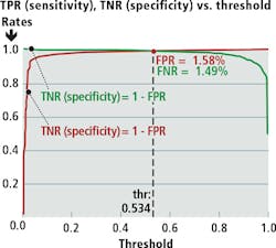
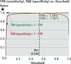
By moving the threshold value towards 1.0, the number of false positives can be reduced at the cost of increasing the number of false negatives, or vice versa. It is then possible to visually check where the system operates by plotting the threshold in the x-axis and both the Specificity or True Negative Rate (= 1 - False Positive Rate) and the Sensitivity or True Positive Rate (= 1 - False Negative Rate) in the y-axis.
The point where the vertical line corresponding to the threshold value cuts both curves yields False Positive and False Negative Rates. A common choice for the threshold value is that which yields approximately equal False Positive and False Negative Rates. For CNN-Surfin', a False Positive Rate of 1.58% and a False Negative Rate of 1.49% were achieved (Figure 6) compared with a False Positive Rate of 17.98% and a False Negative Rate of 18.00% on the SVM version of Surfin', a x12 decrease in the number of classification mistakes made by Surfin'.
The new classifier is now set to be implemented in production environments. Even so, engineers at Tecnalia are working to improve the system with the aim of enabling steel producers to produce steel with zero defects. The 4-class problem (OK versus 3 types of defects), for example, has been evaluated for CNN-Surfin' using a generalization of the AUC (an averaged extension) and it yielded AUC = 0.9956. More samples, however, are currently being gathered to make this number statistically significant.
Since its introduction, the Surfin' system has been delivered to companies such as Tubos Reunidos (Bilbao, Vizcaya, Spain; www.tubosreunidos.com) and Aceros Inoxidables Olarra (Loiu, Bizkaia, Spain; www.olarra.com) where it has enabled production issues to be detected at early stages in the hot process production. Tecnalia is working with other steel production companies to deploy the system to detect more complex shaped steel parts, such as beams with U or H-shaped cross-sections that are used in construction and civil engineering.
Tecnalia has formed a relationship with Sarralle Group (Azpeitia, Gipuzkoa, Spain, www.sarralle.com) to distribute the Surfin' system worldwide.
Antonio Cruz-Lopez, Alberto Lago, Roberto Gonzalez, Aitor Alvarez and José Angel Gutiérrez Olabarria, Machine Vision Engineering Team, Tecnalia, C/Geldo 700, 48160 Derio, Bizkaia, Spain (www.tecnalia.com).
Companies mentioned:
Aceros Inoxidables Olarra
Loiu, Bizkaia, Spain
www.olarra.com
Edmund Optics
Barrington, NJ, USA
www.edmundoptics.com
Laserglow Technologies
Toronto, ON, Canada
www.laserglow.com
Metaphase Technologies
Bristol, PA, USA
www.metaphase-tech.com
Tubos Reunidos Industrial S.A.
Bilbao, Vizcaya, Spain
www.tubosreunidos.com
Teledyne Dalsa
Waterloo, ON, Canada
www.teledynedalsa.com
Tecnalia
Derio, Bizkaia, Spain
www.tecnalia.com
Sarralle
Azpeitia, Gipuzkoa, Spain
www.sarralle.com
