ULTRASOUND SYSTEMS USE TO EXPAND IMAGES
ULTRASOUND SYSTEMS USE TO EXPAND IMAGES
By Lawrence H. Brown, Contributing Editor
Ultrasound systems have evolved to take second place only to x-rays as the most popular medical imaging modality. Originally, ultrasound systems used stationary mechanical positioning arms and multiple transducer arrays that produced extended fields of view (FOVs). These ultrasound systems, known as B-scanners, were replaced in the 1980s with systems that used hand-held transducers to produce real-time images at higher resolution. Using hand-held transducers, however, reduced the FOV so that physicans had to mentally piece together multiple images to obtain contiguous views of the anatomy.
Another continuing problem in designing ultrasound systems was the extremely high data throughput required to render an acceptable image in real time.
Now, as a result of advances in computing power, ultrasound transducers, and real-time operating systems, developers are leveraging the benefits of parallel processing in their next-generation ultrasound equipment. The first such system, the Elegra from Siemens Medical Systems Ultrasound Group (Issaquah, WA), extends the FOV of ultrasound, while maintaining real-time, high-resolution images. Working in conjunction with Yongmin Kim, professor of electrical engineering at the University of Washington (Seattle, WA), designers at Siemens developed a system that uses high-fidelity transducers, analog-to-digital converters (ADCs), and high-performance multimedia processors to capture, process, and display these images.
Ultrasound imaging
Ultrasound images are generated by transmitting signals in the 2-12-MHz range via an ultrasound transducer into the body and measuring echoes from tissue. Ultrasound imaging of the body`s soft tissues began as research in the early 1950s with
single-beam displays (known as A mode displays). An extension of this type of ultrasound, called M mode display, builds up a two-dimensional image over time to show motion articfacts.
By sweeping the beam either mechanically or electronically, two dimensional images can be created. These two-dimensional, or B-mode displays, were static scanners consisting of an ultrasound transducer attached to a mechanical articulated arm. By using the mechanical arm to sweep the transducer of the area to be examined, a two-dimensional image could be created. While the FOV of these transducers was large, these devices were abandoned in the 1980s in favor of real-time hand-held transducers. Although these transducers provided better resolution images, they imaged the body over narrower FOVs.
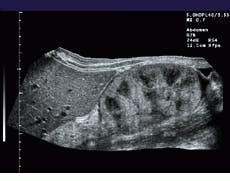
To increase the FOV in its Elegra system, Siemens combines the real-time imaging capability of modern ultrasound transducers with the ability to generate images over large fields of view. To do so, the system registers sequentially acquired image frames, estimates transducer motion, and constructs a panoramic view of the extended FOV in real time (see Fig. 1).
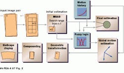
For every new image acquired, its translational and rotational displacements from the previously acquired images are determined. The next acquired image is assumed to have similar features to the previous images, but translated and rotated. Each block in the previous images is compared with the new image. An algorithm, dubbed the XFOV, determines where in the new image each block in the previous image matches best, according to a selected matching criterion, and calculates a relative motion of each block from the previous image to its best matching point in the new image (see Fig. 2). This motion occurs during the time between acquiring the previous image and the new image. The translations computed for each block in the previous images are called motion vectors.
A global translation can be computed from the average of the individual motion vectors, and the rotation can be computed by an analysis of how the motion vectors change between adjacent blocks (see "Fuzzy logic improves motion estimation accuracy" p. 30). Once all the motion vectors are determined, the new image is then translated and rotated accordingly by image warping. The overlapped area is interpolated between the previous image and the current image.
Ultrasound hardware
Ultrasound systems can be divided into a front-end subsystem and a back-end processor. While the front-end is typically used for transmitting and receiving acoustic signals and beam-forming, the back-end converts echo signals into images suitable for display. High-performance ultrasound systems generate vector and raster data in various modes at very high data rates.
To accommodate these modalities, the Elegra system incorporates a processing board that uses two C80 MVP multimedia processors from Texas Instruments (Dallas, TX). Each MVP processor consists of a RISC master processor, four fixed-point processors, and a direct-memory-access (DMA) controller. In the design of the processor board, each RISC processor is used for task coordination among the fixed-point processors and communication with the host processor. Most of the image processing is performed by the fixed-point processors that operate in a multiple-instruction, multiple-data (MIMD) fashion. An on-chip DMA transfer controller controls transferring data between external data memory, on-chip caches, and data RAM.
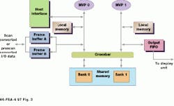
While the first MVP controls host communication and data input, the second controls data output. These two processors are connected to shared memory via a crossbar switch. To process an image, the first MVP inputs an image frame, which is placed in the processors shared memory (see Fig. 3). No geometrical rotation or translation is performed on this image. For each new image that is acquired by moving the ultrasound probe, the geometrical transformation of the image with respect to the first reference image is computed as two translation parameters and one rotation parameter, which represents rotation around the z axis. These three motion parameters define how the new image is rotated and translated and placed in the output image buffer. By using a shared-memory approach and two multimedia processors, this process can be shared in global memory across two processors.
Operations for converting the images to a raster format are performed in a subsystem called the scan converter. Raw vector data are lined up and interpolated and are written to the image-storage buffer for display. Data are then sent to the video controller, which determines how the image is to be displayed (for example, B-mode or Doppler) from a preselected program.
Three-dimensional future
In the past, to expand the diagnostic capability of ultrasound systems required redesigning them as faster processors, and more sophisticated transducers became available. Now, using parallel-processing techniques, such systems can be made modular and less dependent on hardware changes. Indeed, using programmable, parallel processors could cut design cycles in half.
In time, ultrasound systems will provide extended FOVs of three-dimensional images in real time. "Right now, 3-D reconstruction for ultrasound is a technology in search of a purpose," says Pat Von Behren, director of advanced development for Siemens Medical Ultrasound Group. But in six or seven years, he predicts, 3-D ultrasound reconstruction will be the state of the art, as will increased portability of the machines.
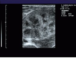
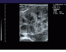
FIGURE 1. To extend the field of view (FOV) of ultrasound, the system registers sequentially acquired image frames and constructs a panoramic view of the extended FOV in real time. A comparision between a standard linear field of view of a renal transplant (bottom) and a wider, panoramic field of view (top) illustrates the effects of the process.
FIGURE 2. To register images, a computational estimate of local motion between successive images is performed. Fuzzy logic simplifies the analysis of the motion of sucessive images using prior-motion history data. This makes the final motion estimation very stable, even when high amounts of image noise are present.
FIGURE 3. In the Elegra`s image-processing board, two TIC80 multiprocessors (MVP 0 and MVP 1) are used to share image rotation translation and scaling tasks in a shared-memory architecture. MVP 1 controls the output of the computed image to the display.
Fuzzy logic improves motion-estimation accuracy
In ultrasound systems, motion vectors can be computed from reflected signals to reduce image artifacts and noise. A variable called the quality factor (QF) indicates the degree of this motion. QF has a level from zero to one. Using conventional reasoning, QF may be considered low when it is below 0.5, and 0.5001 can be considered high. Unfortunately, real situations cannot be so easily classified. Fuzzy logic solves this problem by providing a "gray zone" between high and low values using membership functions to describe variables.
Values of a membership function can range from 0 to 1. If the QF belongs to the "low" category when its level is 0.3 or lower and high when it is above 0.7, the membership function of "QF is low" is 1 below 0.3 and 0 above 0.7. In between, it has value less than 1 but larger than 0. If the membership function has a ramp-down shape between 0.3 and 0.7, the membership value is 0.5 at QF level 0.5.
Membership functions can also be assigned to other variables such as motion consistency (MC) where the output variable provides a measure of the reliability of the motion estimation. In developing fuzzy systems, one rule may specify "if QF is high and MC is high, then the motion estimation is reliable." Additional fuzzy rules can be based on expert or common-sense knowledge with the systems input and output variables connected by fuzzy rules. Rule sets and the shape of membership functions can be adjusted to build systems that behave in specific ways.
If the motion estimation measure is high, the estimated motion vector is correct and is used later in signal transformation. Otherwise, the vector includes error and is mixed with previous estimations to reduce the error. The lower the reliability of the motion estimation, the less current estimation will be mixed with it. If the reliability measure is very low, the best estimation is the previous averaged estimation. Thus, imperfect motion vectors do not affect the display of the final ultrasound image.
Lee Weng
Siemens Medical Systems Ultrasound Group
Issaquah, WA 98027
E-mail: [email protected]
Company Information
Siemens Medical Systems
Ultrasound Group
Issaquah, WA 998027
(800) 361-3569
E-mail: [email protected]
Texas Instruments
Dallas, TX
(800) 477-8924
Image Computing Systems
Laboratory
University of Washington
Seattle, WA 98195
(206) 685-2271
E-mail: [email protected]
