SAR TECHNIQUES GIVE satellite images HIGHER RESOLUTION
SAR TECHNIQUES GIVE satellite images HIGHER RESOLUTION
John H. Mayer, Contributing Editor
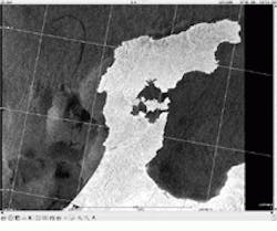
When an aging Russian tanker broke apart off Japan`s west coast last January spilling more than 3700 tons of fuel oil, local disaster agencies needed help. As the leaking fuel oil spread along 400 miles of seacoast, wildlife and the safe operation of 15 coastal nuclear-power plants dependent on sea water as coolant were threatened. One of the first resources officials turned to was imaging data from the Canadian Space Agency`s Radarsat satellite remote-sensing system. Less than five hours after the satellite passed over the west coast of Japan, local authorities received images to help them assess the scope, direction, and potential impact of the spill (see Fig. 1).
Responding to emergencies and disasters in near real time is only a secondary goal of Radarsat. "Because there was major concern about the environmental impact of large tankers on the Arctic, the system was later optimized to detect sea ice," explains Marcel St-Pierre, manager of market development and commercialization for the Canadian Space Agency (CSA; Saint-Hubert, Quebec, Canada).
Long, dark winters
The foremost challenge developers faced was collecting data of remote Arctic terrain. "The long and dark Arctic winter and the country`s long coast line with its frequent cloud cover presented unusual requirements," said St-Pierre. "We needed a system that could cover an area the size of Canada from coast to coast in regions frequently affect ed by clouds and darkness."
Optical satellite remote sensors that depend on sunlight could not meet these requirements. Multispectral sensors such as Landsat collect energy reflected from the Earth`s surface at frequencies equivalent to those of the human eye. Typically, the Earth`s reflected energy is captured in one or more frequency bands, where each band represents a set of frequencies. Image-processing techniques allow these bands to be combined into a multispectral image of the Earth`s surface.
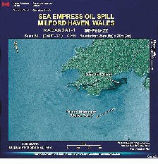
Radarsat is based on synthetic aperture radar (SAR) techniques that use energy transmitted at microwave frequencies. SAR transmits a microwave energy pulse to Earth and then measures the amount of energy that returns to the satellite after it interacts with the Earth`s surface. Unlike optical sensors, SAR can penetrate darkness, clouds, rain, dust, or haze, enabling the satellite to collect data under any atmospheric conditions (see Fig. 2)
Virtual antennas
Synthetic aperture radar improves satellite data resolution by using the motion of the satellite. As Radarsat moves through its orbit at 7 km/s, a 15-m antenna builds a synthetic aperture. To accomplish this, SAR pulses are transmitted as the satellite moves and the return echoes are gathered in an echo store. To compensate for the radar`s movement relative to the ground, echoes are Doppler-shifted as the radar approaches or moves away from a specific area. Doppler-shifted fre quencies are then compared to a reference frequency, effectively increasing the length of the antenna and data resolution. The key to developing SAR images is correctly matching the variation in Doppler frequency for each point in the image. This process requires precise tracking of the relative motion between the satellite and the imaged object.
Radarsat`s SAR antenna operates at a single microwave frequency know as C-band (5.3-GHz frequency or 5.6-cm wavelength). The system generates a single channel of data or a one-channel image that can be combined with multidate Radarsat data or data from other sources to create color images.
The satellite relies on a horizontal-transmit/horizontal-receive (HH) polarization system that transmits its C-band microwave energy in a horizontal orientation and then captures the returned energy in the same manner. Variations in the returned signal, or backscatter, indicate surface roughness and topography and physical properties such as moisture content. Transmitting and receiving a horizontally polarized signal is a tremendous benefit for ocean applications. Less sensitive to interference from slight wind disturbances on the ocean surface, HH polarization allows Radarsat to monitor sea ice even in very rough seas.
Synchronous orbits
Key to imaging the arctic is Radarsat`s near-polar, sun-synchronous 798-km orbit. Circling the earth 14 times per day, the satellite crosses the equator at dawn and dusk, virtually ensuring its solar arrays remain in continuous sunlight. The satellite`s orbit provides daily coverage of the entire Arctic region and allows any part of Canada to be viewed within three days. It can also achieve complete coverage at equatorial latitudes every six days using a 500-km-wide swath. And its polar orbital configuration allows researchers to view regions in South America, Africa, and Asia never before mapped by radar.
With each orbit, SAR can capture 28 minutes of data and image up to 1.1 million square kilometers of the Earth`s surface. Data are downlinked in real time to receiving stations or data-reception facilities in Gatineau, Quebec; Prince Albert, Saskatchewan; and Fairbanks, Alaska. If the spacecraft is not within range of these stations, image data are stored on one of two recorders on the satellite that can store up to 10 minutes of SAR data or enough data to record imagery of 420,000 sq km.
Imaging data are downlinked over X-band radio-frequency links at 8105 MHz. Real-time data can be transmitted at a rate of 105 Mbit/s, while a second data link at 8230 MHz is available to transmit tape-recorded data at 85 Mbit/s. The system can simultaneously transmit both real-time and recorded data using both links.
Processing data
To meet a range of requirements, Radarsat data can be processed in one of six ways. Researchers can acquire raw signal data that require extensive processing before being viewed as an image. Alternatively, if they want to test SAR processing algorithms or develop techniques that use phase preservation, they can acquire data pixels in phase and quadrature form.
Data are also available as standard map projections. For users who require maximum resolution and do not require position accuracy or near-real-time response, Radarsat also offers Path Image and Path Image Plus. Unlike most Radarsat imagery that is stored as 16-bit data, these two products are compressed to 8-bit data. Path Image Plus products have smaller pixel spacing than Path Image products and are therefore optimal for identifying point targets.
Beam steering
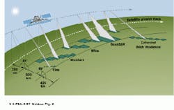
Probably the most significant difference between Radarsat and other satellite-mounted SARs is the variety of beam modes it offers. All of Radarsat`s predecessors offered a single incidence angle and resolution size. Radarsat is the first SAR with an antenna beam that can be electronically steered to provide a choice of swath widths, spatial resolutions, and angles of incidence. The beam can be steered to use incidence angles in the range of 10 to 60 in 50- to 500-km swaths. By offering operating modes with spatial resolutions from 10 to 100 m, images can be generated that distinguish streets or buildings.
Beam modes range from fine, standard, and wide to special ScanSAR and extended functions. Operators can select resolutions from 8 to 100 m and image width from as little as 50 km to as much as 500 km; as the resolution improves image width shrinks. Each beam mode can be placed in various positions across a wide path.
Because of the SAR`s seven beam modes and 25 beam positions, ground controllers can program the satellite for wide-area coverage for applications such as ocean monitoring or narrowly focus the signal to acquire high-resolution imagery for agricultural or forestry needs. "It`s the only SAR system with that kind of capability," noted St-Pierre. "We can cover a swath of more than 500 km or, in fine resolution mode, get an image with a resolution down to 8 m in a swath of about 50 km."
An adjustable incidence angle offers additional benefits. While the SAR beam transmits at a right angle to the satellite path, it can be adjusted to provide a variety of steep and shallow incidence angles. This capability opens up opportunities to maximize image data. Shallower angles are more effective at detecting subtle land features in areas of low topographical relief, while steeper angles can effectively image valleys in mountainous terrain.
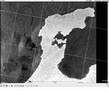
FIGURE 1. Earlier this year, image data from Radarsat helped local officials assess the scope and impact of an oil spill off the west coast of Japan, near Hakui.
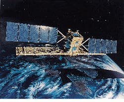
Dominating the Radarsat design is a 4-ft-long SAR antenna and two large solar arrays. X-band radio links are used to download image data.
FIGURE 2. To collect data in heavy cloud cover or fog, Radarsat designers use a synthetic aperture-based imaging system rather than an optical remote sensor. This image of an oil spill off Milford Haven, Wales, taken in February 1996 in early morning fog, demonstrates the radar`s capability regardless of weather conditions.
Using radar signatures to interpret satellite data
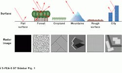
Unlike optical imagery, where surface feature characteristics impact the reflection of energy in many wavelengths and are displayed in the image as a series of colors, radar signals interact with ground features based on their size, shape, surface roughness, and other physical aspects. Because radar operates in only a single wavelength, however, the interaction between the signal and the surface is represented by the tone, texture, and density of a black and white image.
Each pixel in an SAR image represents the radar backscatter for the corresponding area on the ground. Dark areas in an image indicate low backscatter, while bright areas depict high backscatter. The brighter the image, the more energy is reflected back to the radar.
A number of conditions influence the degree of backscatter for a specific target area. The moisture content on the target, the polarization of the pulses, the observation angle of the radar, and the size of the scatters in the target all impact the amount of microwave energy reflected back.
Flat surfaces reflect little or no energy and appear as dark images. While wet surfaces generally appear brighter than dry surfaces, a smooth body of water reflects incoming pulses away from the target and appear dark. Vegetation generally appears gray or light. The more a surface is inclined toward the radar, the stronger the backscatter, and brighter the image. (Image courtesy Tony Freeman, Jet Propulsion Laboratory)
Beam switching extends swath width
While Radarsat can access a 500-km-wide region of the Earth across its three types of beams, the widest area any individual beam can access is only 150 km. "Many people, especially those working in ice operations or coastal and ship monitoring, would like to see an image that`s 500 km wide," says Ken Lord, mission operations planning manager at the Canadian Space Agency (Quebec, Canada).
To extend the swath coverage in a single satellite pass, the designers of Radarsat incorporated a mode called ScanSAR that takes advantage of the rapid beam-switching capabilities built into the antenna design. In ScanSAR mode, the antenna beam switches between a number of contiguous areas. The beam dwells long enough on each area to allow a synthetic aperture to form from the series of pulses transmitted and received, but switches fast enough to guarantee that the system cycles to cover the entire area without a break in coverage.
The system offers four different combinations of beams, but the most commonly used are two wide beams for 300-km total coverage and four beams to generate 500-km-wide images. "The result is an image 500 km wide but made up of three or four different beams," says Lord.
The way the signal is obtained--in discrete blocks of pulse returns from different subswaths of the total image--requires special processing and limits image quality. Azimuth resolution is limited to about 30 m for the two-beam operations and to about 60 m for the four-beam approach. There is an inherent variation in the image quality across multiple beams. While the data can produce images of different combinations of resolutions, the system can also generate a standard uniform image through some spatial averaging of pixels for those applications where wide coverage is of primary importance.
Radarsat offers a variety of beam modes ranging from fine mode, which offers resolution under 10 m but over a narrow 50-km-wide area, to large, regional ScanSR modes, which can cover areas up to 500 km wide. An electronic steering system allows individual beams to be steered to any of seven different positions across a 500-km accessibility swath.
