Solar blind filters enhance ultraviolet imaging
Samuel Pellicori
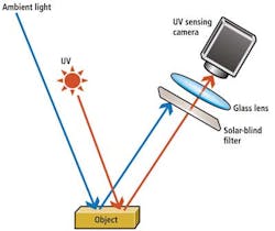
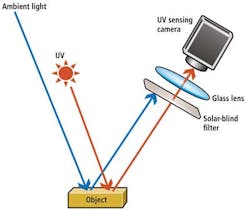
Ultraviolet (UV) fluorescence imaging is a commonly used technique that requires a UV source to stimulate visible fluorescence and filters placed in front of the camera that block UV wavelengths while allowing fluorescing light in the visible spectrum to be recorded. An alternate detection technique, UV reflectance imaging, records the reflected UV image while blocking visible background and fluorescent emission from the object (Figure 1). Applications of reflected UV imaging include forensics, medical imaging, pollution and climate monitoring and surface damage inspection.
To provide the UV illumination for such applications, a number of different sources can be used. Artificial sources of UV energy include mercury vapor lamps with UV lines at 254 nm and 365 nm, but strong visible emission lines are present at 404 nm, 435 nm, 546 nm and 615 nm wavelengths. Xenon arc lamps emit UV as well as visible and near-IR light. To perform UV imaging requires high rejection of the non-UV light from these sources and from other ambient sources such as sunlight and fluorescent lighting. LEDs at 365 nm and other UV wavelengths can be used as UV illumination sources; in this case only ambient light needs to be rejected.
UV imaging previously relied on photographic filters composed of visible-absorbing glasses and therefore was limited to UVA (400-320 nm) and UVB (320-280 nm) wavelengths. All of these visible-absorbing glass filters begin to transmit longer wavelengths, specifically red and near-IR light, and therefore cannot produce high contrast UV images. This is an especially severe problem when using cameras with CMOS or CCD arrays that may have at least three times the response in the near-IR that they do in the near 300 nm. UV imaging may also suffer from insufficient elimination of long wavelength light from background sources.
Eliminating long wavelengths
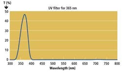
To eliminate such long-wave transmission and capture the UV energy reflected or absorbed by objects while eliminating ambient lighting requires a solar blind filter that that has transmission in the spectral range shorter than approximately 400 nm and rejects light between approximately 400-1100nm. Figure 2 shows the in-band transmission measured for a solar-blind filter with its spectral pass-band centered at 365 nm that has been developed by Pellicori Optical Consulting (Santa Barbara, CA, USA) in corroboration with Optical Filter Source (Austin, TX, USA;www.ofs-online.com).
Solar-blind filters are composed of a pass band-defining filter, typically an interference filter, and a means of rejecting non-UV light to optical densities (ODs) >6, and some applications require an OD of 9. The rejection level depends on the source UV intensity relative to the background out-of-band spectral intensity. UV transmitting interference filters can be manufactured for essentially any UV pass bands center wavelength and any spectral bandwidth to define specific pass bands in the UVA (400-320 nm), the UVB (320-280 nm - the limit of atmospheric transmission), or the UVC (280-225 nm) regions. Specific applications operate in these different UV regions.
Filters for the UVA and UVB regions are constructed by combining interference-type filters that reflect the visible and NIR solar energy while transmitting the UV passband with visible-absorbing glass filters. No similar functioning absorbing glasses exist that transmit the UVC wavelengths, therefore the high rejection that produces solar blindness in the UVC region must be accomplished entirely with multiple interference-type reflecting stacks to reject 400-1100 nm wavelengths. Improved deposition technology for thin films has permitted higher transmissions to be achieved, especially for the UVC wavelengths. The result is the ability to fabricate UVC interference coatings with minimum absorption of UV and therefore higher in-band transmission.
High contrast UV imaging
High-contrast UV images can be captured by using a solar blind filter with an appropriate light source and monochrome CMOS camera. Many normal glass photography lenses have sufficient transmission of UVA and UVB wavelengths to permit imaging of the reflected UV. Special (expensive) UV lenses made from fused silica and calcium fluoride elements are required for imaging UVC.
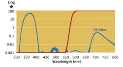
Figure 3 shows the out-of-band transmissions measured for the solar-blind filter of Figure 2. To check for out-of-band leaks, an OG590 UV blocking visible-transmitting filter from SHOTT North America (Elmsford, NY, USA;www.us.schott.com) is inserted in the optical path. As can be seen, the solar-blind filter rejects the visible light that may be present from visually fluorescentmaterials or from ambient light. The filter can therefore be used in a sunlit environment.
Forensic application examples
To show that long-wave out-of-band energy is rejected to a high level, images of the solar disk were made with a UV-blocking visible-transmitting filter and with the solar-blind 365 nm filter. In Figure 4b, a SCHOTT OG590 glass filter is mounted in front of a CMOS camera thus blocking all UV wavelengths. That glass filter absorbs all light short of 550 nm. In Figure 4a, the sun is imaged with the 365 nm solar blind filter. As can be seen, only UV light is imaged and no long-wavelength light is detected.
One of the applications where UV reflectance imaging proves useful is forensics. Figure 5 clearly show the advantages of using a solar blind filter. In Figure 5, the ability to image latent finger prints by UV is compared with imaging in visible light. Figure 5a is the visible image; 5b is the UV image. Confusing background light is eliminated by the solar-blind filter, and the print contrast is thereby enhanced. Such solar blind filters permit imaging systems to be used in high ambient lighting conditions with UV illumination.
Samuel Pellicori, Optical Engineer, Pellicori Optical Consulting (Santa Barbara, CA; USA)
Companies mentioned
Optical Filter Source
Austin, TX, USA
www.ofs-online.com
Pellicori Optical Consulting
Santa Barbara, CA, USA
[email protected]
SCHOTT North America
Elmsford, NY, USA
www.us.schott.com
Vision Systems Articles Archives


